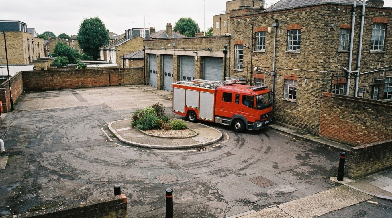
A fire station access is only as credible as the appliance used to test it. In England, the Ministry of Housing, Communities and Local Government’s Approved Document B gives typical minimums of 3.7 metres for a pumping-appliance road width and turning circles of 16.8 metres kerb-to-kerb and 19.2 metres wall-to-wall. The typical minimum gateway width is 3.1 metres.
Those benchmarks are a starting point, not a substitute for testing the vehicle that needs to use the site. Fire and Rescue Services operate different fleets, so choosing a representative appliance matters, especially where access is constrained. A swept path analysis for a fire station access models the vehicle’s turning movements and overhangs against the layout, showing whether it can manoeuvre without conflicting with obstructions or other users of the space.
This article explains how vehicle geometry, clearances and access widths shape the assessment, and why the appliance selected can affect the result. It also covers what a useful swept-path drawing should show and how professional analysis can inform decisions about a proposed or changing fire station layout.
Key Takeaways
- Understand why rear-wheel tracking and vehicle overhangs shape the space a fire appliance needs to turn.
- See how a swept-path drawing can reveal conflicts with obstructions, parked vehicles and pedestrian or cycle areas.
- Learn why road and gateway widths must be considered alongside turning geometry and vertical clearance.
- Recognise how selecting an appliance that represents the relevant Fire and Rescue Service fleet affects the assessment.
- Find out how professional swept path analysis can support planning and layout decisions for fire station access.
Swept path analysis definition and vehicle turning geometry
At a fire station, access design must accommodate the appliance’s complete turning movement, not just its body width. Swept path analysis models the vehicle’s route through an entrance, turn or training area and shows whether the layout provides sufficient manoeuvring space.
Swept path geometry
Swept path analysis models the space a vehicle occupies while turning, including the different arcs traced by its wheels and body. The rear wheels follow a tighter arc than the front wheels, while body overhangs can extend beyond the wheel paths.
This matters at a fire station entrance, where a vehicle may need to turn close to a wall, gate or parked appliance. A drawing that shows only the vehicle’s centreline can miss conflicts at its edges. The complete turning envelope gives designers a clearer basis for assessing the layout.
Turning circles and route layouts
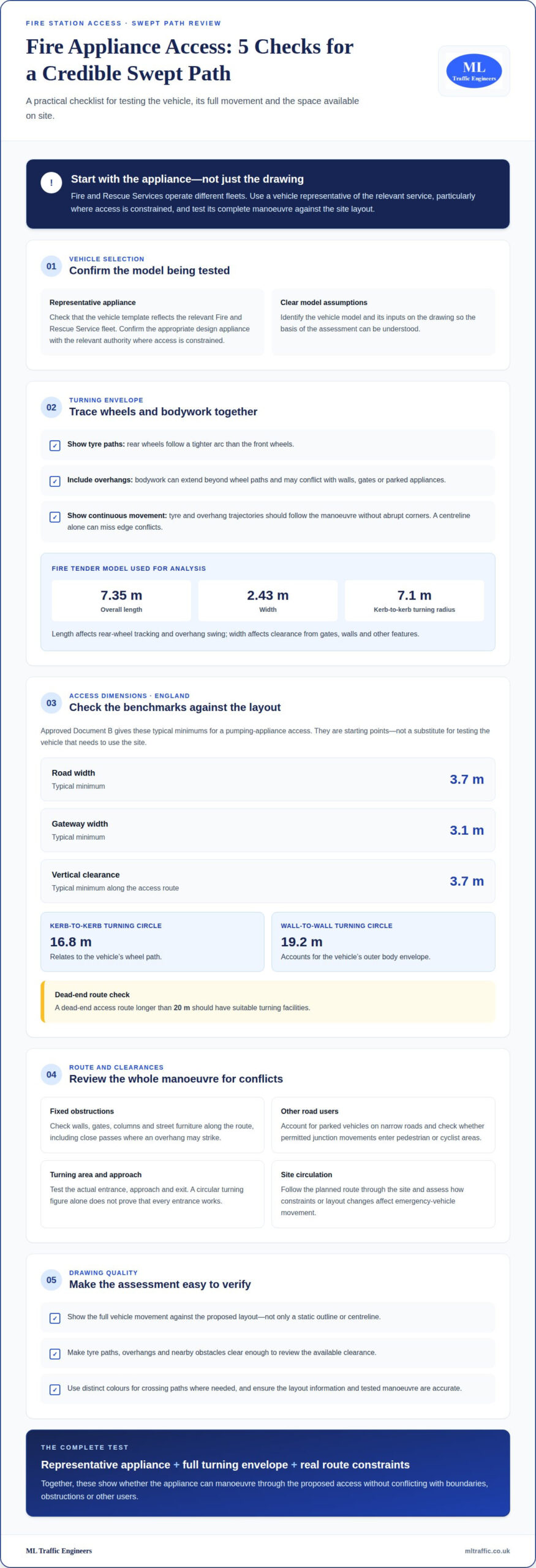
Turning circles describe the space a pumping appliance needs to complete a turn. In England, Approved Document B gives a typical minimum kerb-to-kerb turning circle of 16.8 metres for a pumping appliance, and a typical minimum wall-to-wall turning circle of 19.2 metres.
The kerb-to-kerb measurement relates to the vehicle’s wheel path; the wall-to-wall circle accounts for its outer body envelope. A dead-end access route longer than 20 metres should have suitable turning facilities. At a training facility, analysis can test whether the layout accommodates worst-case vehicle turning requirements, including repeated manoeuvres.
Fire tender dimensions and turning radius
A Fire Tender model used for analysis has an overall length of 7.35 metres, a width of 2.43 metres and a kerb-to-kerb turning radius of 7.1 metres. These dimensions affect how much space the vehicle needs at an entrance and through a turn.
Vehicle length influences the rear wheels’ path and the swing of the front and rear overhangs. Width affects clearance from gates, walls and other features. Modelling these dimensions together helps identify whether any part of the vehicle crosses a boundary, even when its wheels remain within the road.
Applicable guidance and site requirements
In England, Approved Document B provides fire-appliance access guidance, including the turning-circle benchmarks above. The relevant Fire and Rescue Service’s fleet also matters because services operate different vehicle types. Where access is constrained, confirm the appropriate design appliance with the relevant authority.
The turning area needed at a fire station entrance depends on the selected appliance and the geometry of its approach and exit. Analysis should show the full manoeuvre: a circular turning figure alone does not prove that every entrance works. Local requirements can influence the vehicle model and layout being assessed.
For a closer look at how vehicle geometry appears on drawings, this AutoTURN swept path analysis guide explains the modelling context. The resulting assessment connects the chosen vehicle’s dimensions with the access route and available turning space.
Vehicle envelope and clearance from obstructions
A vehicle envelope shows the area an appliance occupies as it moves, including its wheels and overhanging bodywork. The drawing should track continuous movement, with no abrupt corners in the tyre or overhang trajectories. This helps identify conflicts that a centreline or static vehicle outline can miss.
For UK fire-appliance analysis, use a vehicle template representing the relevant Fire and Rescue Service appliance. Vehicle-tracking software simulates its movement and displays tyre paths and overhangs against the proposed layout. The drawing should identify the model inputs so the assessment’s assumptions are clear.
Common failures include a wheel path crossing a kerb, an overhang striking an obstruction, or an appliance needing more room than the available turning area. A clear assessment shows the full manoeuvre and any obstacle along the route. England’s Approved Document B gives 3.7 metres as the typical minimum vertical clearance for a pumping-appliance access route.
Obstructions include walls, gates, columns, street furniture and parked vehicles. On narrow roads, account for parked vehicles because they reduce usable space. The analysis should also show whether the vehicle can complete permitted junction movements without entering pedestrian or cyclist areas.
Site layouts may need to accommodate emergency vehicles alongside other expected traffic. The assessment should follow the planned route and its constraints, identifying whether an entrance, junction or internal road creates a conflict. This is relevant to fire stations and hospitals, where changes to circulation can affect how emergency vehicles move through the site.
The quality of a simulation depends on the selected vehicle, accurate layout information and the manoeuvre being tested. A professional models the intended route, checks the tyre and overhang paths, then reviews clearances against nearby features. Where paths cross on a drawing, distinct colours can make each trajectory easier to read.
Where a proposed layout needs a clear vehicle movement assessment, a professional swept-path review can show how the modelled appliance interacts with site constraints.
Review the vehicle’s complete route rather than assessing the entrance or turning area in isolation. The relationship between the modelled movement and fixed features should be easy to verify, including where the route passes close to an obstruction. Edmonton guidance says the swept path analysis should clearly show that no obstacles or obstructions exist along the vehicle’s movement path. This makes it possible to see whether the plotted route is clear throughout the manoeuvre, not just at its start and finish.
The vehicle selected for the check should also reflect the vehicles expected to use the layout. Leicestershire swept-path analysis must show that 11.2 m long refuse vehicles can navigate the road layout and turning heads, unless the borough or district uses a larger vehicle. Leicestershire road layouts must be checked after swept-path analysis to confirm expected vehicles can manoeuvre safely and effectively without overrunning kerbs. The same kind of movement assessment is used to check that emergency vehicles can access and leave fire stations, hospitals and NHS trust sites efficiently. Together, these checks help establish whether the proposed circulation works for the relevant vehicles and whether the drawn paths remain within the intended road space. A complete review therefore considers vehicle size, turning requirements, clear movement paths and the effect of the manoeuvre on kerbs.
Swept path analysis for emergency service developments
A new fire station, a revised entrance or an altered internal route can change how emergency vehicles move through a site. A swept path analysis for a fire station access tests a proposed layout against the intended appliance and its required movements. Provide the site plan, vehicle information and operational routes to assess, giving the professional a defined basis for modelling.
Begin by identifying the access movements that matter, such as entering from the public road, circulating around the site, reaching an operational area and exiting. For example, a design may allow forward entry but require reversing to leave. Modelling both movements helps reveal whether the layout supports the intended site operation.
Vehicle choice should reflect the Fire and Rescue Service expected to use the site. Services in England operate different fleets, so the selected appliance can affect the result, especially where the entrance is constrained. A swept path analysis for a fire station access should make the vehicle model and movement assumptions clear on the drawing.
Site information should also reflect features that could shape movement. The professional considers the proposed road layout, gateways, boundaries, internal circulation and planned or likely parking. For an existing station, the assessment can focus on a specific change, such as moving an entrance or adjusting the circulation route, rather than treating the site as an entirely new development.
Fire-fighting infrastructure can also influence the route being assessed. In England, where a dry fire main is provided, Approved Document B guidance requires pumping-appliance access within 18 metres of the inlet connection point. Showing the inlet and relevant approach on the plan helps relate vehicle access to this site feature.
Emergency-service projects may also involve hospital sites. Swept path analysis has been used for new hospitals and existing hospital sites where layouts are changing, to assess whether emergency vehicles can manoeuvre as required. A swept path analysis for a fire station access follows the same core principle: assess the intended vehicle movements against the actual proposed layout.
The drawing should communicate the tested route and model inputs so project teams can understand what the assessment demonstrates. This helps them discuss layout changes while plans are still being developed. For a station project, commissioning swept path analysis for a fire station access brings vehicle selection, site information and intended manoeuvres together in one focused assessment.
Access road and gateway widths
Road and gateway dimensions set the physical limits for a pumping appliance before turning geometry is assessed. Approved Document B gives 3.7 metres as the typical minimum road width for a pumping appliance in England, according to the Ministry of Housing, Communities and Local Government. The typical minimum gateway width is 3.1 metres. These are separate measurements, so a road that meets its benchmark can still lead to a restricted entrance.
Clear width matters more than the apparent distance between boundary lines. A gate leaf, wall return, column or other fixed feature can reduce the space available to the vehicle. At a fire station entrance, consider both the approach and the point where the appliance passes through the gateway. The vehicle’s swept movement may need more room than a straight approach.
England’s typical minimum vertical clearance for a pumping-appliance access route is 3.7 metres, and the typical minimum load-bearing capacity is 12.5 tonnes. These factors address different constraints: overhead obstructions can restrict access even where the road is wide enough, while the route surface must support the appliance. A clear plan should show overhead features and the intended access route.
Consider width through bends, junctions and turning heads as well. A route may narrow at a pinch point, or a vehicle may need additional lateral space while negotiating a turn. Swept-path modelling can compare the appliance’s wheel and body trajectories with kerbs, walls and boundaries. This shows where the layout constrains movement, rather than relying only on a width measured along a straight section.
At a gateway, the approach angle and the position of the opening affect the manoeuvre. For example, an appliance turning towards a gate may need to track close to one side before its rear clears the opposite edge. The drawing should represent the gate and adjacent obstructions, then show the vehicle’s complete movement through the entrance. A nominal opening measurement alone cannot demonstrate that the manoeuvre works.
Read road width, gateway width, vertical clearance and load-bearing capacity together. A route that meets one dimensional requirement may still be constrained by another feature, such as a low canopy or an offset entrance. The design assessment should identify each relevant constraint and show how the selected appliance moves along the full access route.
These measurements provide a basis for reviewing access, but the vehicle model and site layout determine how the route performs in practice. A professional assessment brings road and entrance dimensions together with the appliance’s movement, helping the design team identify where the access arrangement may need to change.
Selecting a representative fire appliance for swept path analysis
The vehicle model determines which movements the assessment can reliably test. Fire and Rescue Services in England operate different fleets, so a model suited to one service may not represent another. For constrained access, confirm the appropriate design appliance with the relevant authority before assessing the layout.
A professional selects a model to match the site’s intended operational use, not simply because it represents the largest vehicle available. The key question is whether the appliance expected to use the access can complete its required movements. At a station serving a particular Fire and Rescue Service, that service’s fleet is the relevant starting point.
Vehicle selection should reflect the manoeuvres the site needs to accommodate. A station entrance may require an appliance to turn in from the adjoining road, pass through a gateway, circulate within the site and leave again. A training area may also need assessment for specific vehicle movements. Each scenario can place different demands on the layout.
A professional assessment therefore brings together:
- The operating context: identify the Fire and Rescue Service and the access or facility being assessed.
- The design appliance: use a vehicle representative of the service’s fleet, particularly where the route is constrained.
- The required movements: model the actual entrance, internal circulation, turning or exit manoeuvres.
- The site layout: use the proposed access geometry and show relevant boundaries and obstructions.
These decisions connect the vehicle template to real site conditions. For example, an appliance may fit through a gateway on a straight approach but need more manoeuvring room when turning into it. A professional tests the complete movement, considering how the vehicle approaches, passes through and clears the entrance.
Make the selected model and its inputs clear on the drawing. This allows reviewers to understand which appliance the analysis represents and what movement was tested. If the service’s expected vehicle differs from the model used, the drawing may not answer the access question the project needs to resolve.
The practical takeaway is to select the appliance from the relevant service’s operational context, then test the movements the site must support. For constrained layouts, agreement on the design vehicle is especially important. Arrange a swept path assessment to evaluate how the chosen appliance moves through the proposed access.
ML Traffic Engineers UK: Swept Path Analysis
ML Traffic Engineers UK provides Swept Path Analysis for proposed fire station access layouts and sites where vehicle movements need assessment. The analysis links the selected appliance and its manoeuvres to the site plan, helping identify access constraints for consideration during planning.
This service can support a new development or a change to an existing layout, particularly where an entrance, turning area or internal route must accommodate a fire appliance. The assessment gives project teams clear vehicle-movement information to inform design decisions.
For professional assessment of your proposed access, contact ML Traffic Engineers UK.
Move your access design towards the next decision
The next step is to use the vehicle assessment as part of the wider planning conversation. A clear project brief can link the proposed access, operational movements and design decisions, helping the project team identify what needs attention before the layout advances. For a fire station project, commissioning swept path analysis for a fire station access provides focused evidence for that discussion.
ML Traffic Engineers UK provides Swept Path Analysis, Transport Statements and Parking Surveys. These services support different transport-planning needs as a project develops, with the appropriate work depending on the questions the scheme needs to address.
Contact ML Traffic Engineers UK to discuss your project and take the next step with a clear view of your access design.
Frequently Asked Questions
What is swept path analysis for fire station access?
Swept path analysis tests whether an appliance can use a particular access layout. For example, a model can show whether a fire tender can enter a station from the adjoining road and clear a gate while turning. The drawing helps the design team identify where kerbs, boundaries or site features affect the planned route, then consider layout changes before the access design progresses.
What are the dimensions and turning radii of common UK fire appliances?
Fire and Rescue Services in England operate different fleets, so there is no single set of dimensions for every appliance. One Fire Tender model used in swept-path analysis is 7.35 metres long, 2.43 metres wide and has a 7.1-metre kerb-to-kerb turning radius. These figures describe that model, not all UK fire appliances. The relevant service’s vehicle should inform the design assessment, especially where access is restricted.
What information is needed to commission a fire appliance swept path assessment?
Provide the proposed site layout, access arrangement, relevant vehicle information and the movements the design needs to accommodate. Identify features that could affect the route, such as gates, walls, parking areas or internal circulation routes. If the site is changing, include the proposed layout rather than relying on an earlier arrangement. This gives the assessment a defined vehicle, route and set of manoeuvres to test.
Which vehicle templates and software are used for UK fire appliance swept path analysis?
Use a vehicle template that represents the appliance operated by the relevant Fire and Rescue Service, and confirm the design appliance with that authority where access is constrained. Vehicle-tracking software models its movement and displays tyre paths and overhangs; the drawing should identify the model inputs.

Disclaimer
The content on mltraffic.co.uk, including all technical articles, guides, and resources, is provided for general informational and educational purposes only. It is not intended to constitute professional advice in traffic engineering, transportation planning, development approvals, or any other technical or legal field.
While ML Traffic Engineers makes every reasonable effort to ensure the accuracy, completeness, and timeliness of the information published, we do not provide any warranties or representations (express or implied) regarding its reliability, suitability, or availability for any particular purpose. Any reliance you place on the content is strictly at your own risk.
In no event shall ML Traffic Engineers, its directors, employees, authors, or affiliates be liable for any direct, indirect, incidental, special, consequential, or punitive damages (including, without limitation, loss of profits, data, or business opportunities) arising out of or in connection with the use of, or inability to use, any information provided on this website.
The articles and guides on this site are not a substitute for engaging a qualified, professional traffic engineer to assess your specific project requirements. For tailored advice, compliance assessments, or traffic engineering services, please contact a competent professional.
This disclaimer may be updated from time to time without notice. By accessing or using this website, you agree to be bound by the most current version of this disclaimer.