What if you could satisfy a rigid Local Highway Authority while protecting your site’s developable area? Many developers view the sight line assessment manual for streets as a restrictive barrier that forces them to sacrifice density for safety. It’s a common frustration to feel that complex Stopping Sight Distance formulas are working against your project’s commercial viability.
We understand that precision is a functional necessity in these high-stakes environments. You need a layout that maintains public safety while passing rigorous regulatory scrutiny. This guide will show you how to master the technical requirements of visibility splays to secure planning approval without highway safety objections. We’ll explore the current standards for streets with speeds below 37mph, clarify the 2.4-meter X-distance rule, and provide a clear framework for creating defensible diagrams that highway officers respect. We’ll break down the critical distinction between Manual for Streets and the updated DMRB standards. You’ll learn how to apply technical guidance accurately to develop a professional strategy for your next Transport Statement or Transport Assessment.
Key Takeaways
- Differentiate between Manual for Streets and DMRB requirements to ensure your visibility splays meet the specific speed thresholds required by Local Highway Authorities.
- Master the technical calculation of X and Y distances to produce a robust sight line assessment manual for streets that maximizes your site’s developable land.
- Identify and mitigate common urban obstructions using established visibility height rules to maintain safety without compromising site density.
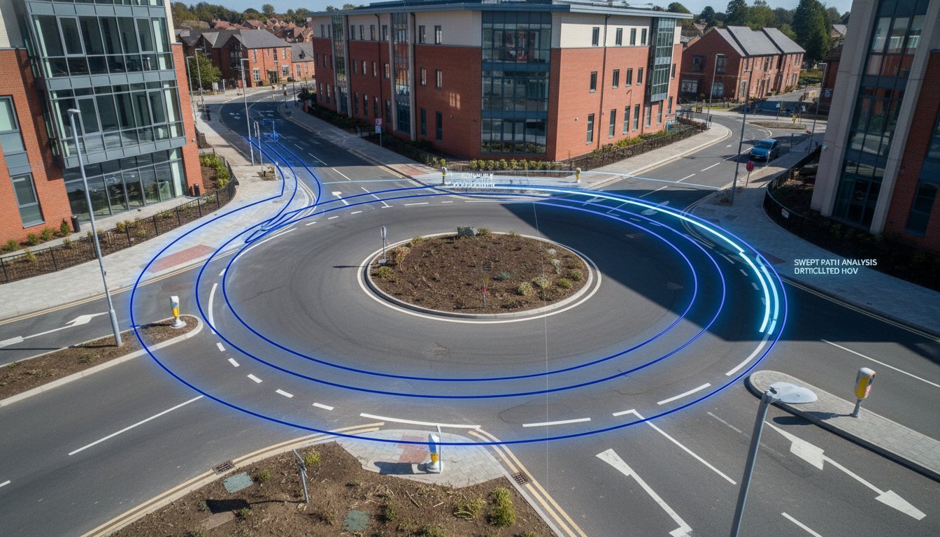
- Streamline your planning process by combining sight line assessments with Swept Path Analysis to verify junction geometry before submission.
- Reduce the risk of costly post-approval redesigns by achieving CAD-level accuracy in your initial visibility splay diagrams.
What is a Sight Line Assessment in Manual for Streets?
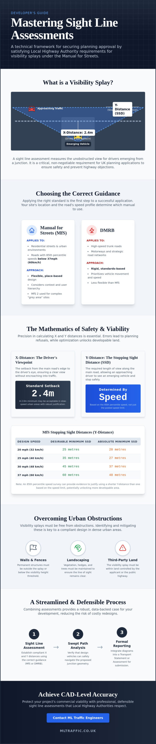
A sight line assessment is the technical process of measuring the unobstructed view available to drivers at a junction or property access. It ensures that those emerging from a minor road can see approaching traffic clearly enough to join the main flow without causing a collision. Conducting a professional sight line assessment manual for streets is now a non-negotiable requirement for UK planning applications in 2026. Precision here is vital. A small error in calculation often leads to a highway safety objection that stalls your entire development.
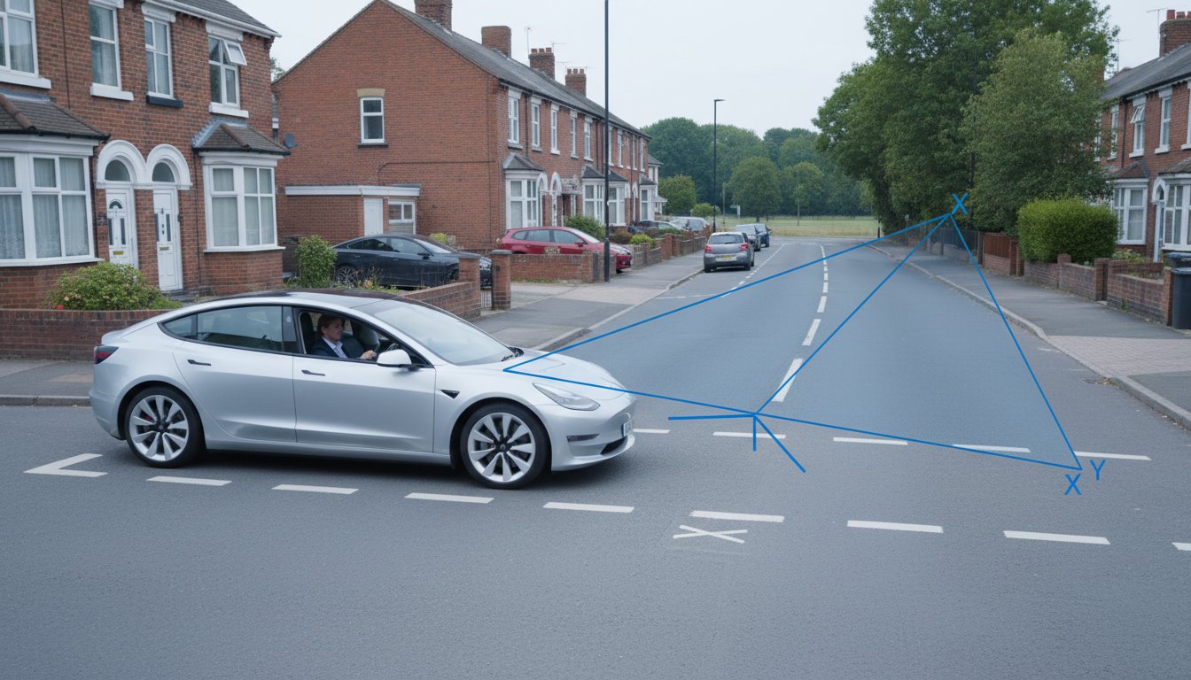
In highway engineering, we define these visibility splays using “X” and “Y” distances. The “X” distance represents the driver’s eye position, measured back from the edge of the running carriageway. For most residential developments, 2.4 metres is the standard setback. The “Y” distance is the length of the view along the main road. This length is determined by the recorded or design speed of the traffic, known as the Stopping Sight Distance (SSD).
Manual for Streets vs. DMRB: Which Applies to You?
Choosing the correct guidance is the first step in any successful application. Manual for Streets (MfS) applies to residential streets and urban high streets where 85th percentile speeds are below 37mph (60km/h). If your project involves high-speed trunk roads or motorways, you must follow the Design Manual for Roads and Bridges (DMRB). While the DMRB is more rigid, MfS allows for a flexible, place-based approach. For those complex “grey area” sites that don’t fit neatly into either category, Manual for Streets 2 (MfS2) provides the necessary technical bridge to justify your design to the Local Highway Authority.
The Legal Necessity for Visibility Splays
Local Highway Authorities (LHA) use sight lines as a primary metric to judge the safety of a proposed access. If a splay is obstructed by third-party land or permanent structures, the LHA will likely recommend refusal on safety grounds. Under the National Planning Policy Framework (NPPF), developments must ensure safe and suitable access for all users. We integrate these assessments directly into our Transport Statements and Transport Assessments to provide the data-backed evidence planners demand. Without a clear, defensible splay diagram, your project faces significant regulatory risk.
Calculating Visibility Splays: The X, Y, and SSD Components
Precision is the foundation of a defensible sight line assessment manual for streets. When we calculate these splays, we aren’t just drawing triangles on a map. We’re applying mathematical certainty to ensure highway safety while protecting your site’s developable area. The visibility splay consists of three core components: the X-distance, the Y-distance, and the resulting Stopping Sight Distance (SSD). Errors in any of these three variables can lead to a planning refusal or costly Section 278 redesigns later in the project lifecycle.
One of the most effective ways to optimise your site layout is through an 85th percentile speed survey. Many developers assume they must design for the posted speed limit. However, if actual traffic speeds are lower than the limit, a professional Traffic Survey can provide the evidence needed to justify a shorter Y-distance. This approach often unlocks land that would otherwise be lost to oversized visibility splays. We use this data to create a technical argument that Local Highway Authorities find difficult to ignore.
Determining the Correct X-Distance
The X-distance is the setback from the edge of the main road to the driver’s eye. In the UK, 2.4 metres is the standard setback for most residential and commercial junctions. This distance is critical because it allows a driver to see approaching traffic without the front of their vehicle protruding into the path of oncoming vehicles. While a 2.0-metre minimum is sometimes acceptable for very low-volume sites or slow-speed urban environments, it’s a “minimum” rather than a target. Using a 2.0-metre setback requires robust justification, as it can impact driver psychology and pull-out safety by forcing vehicles closer to the live carriageway.
Mastering the Y-Distance and SSD
The Y-distance represents the length of the splay along the main road, which must equal the Stopping Sight Distance (SSD). We use Table 7.1 from the Manual for Streets to match recorded speeds to the required visibility length. For example, at 30mph, the standard SSD is typically 43 metres. However, this calculation must account for driver eye height (1.05m to 2.0m) and object height (0.6m to 2.0m) to ensure a clear line of sight to a small child or a low vehicle. Gradients also play a major role. If the main road has a significant downhill slope, the braking distance increases, and your sight line assessment manual for streets must reflect a longer SSD to remain valid.
Overcoming Urban Constraints and Obstructed Sight Lines
Urban developments rarely provide a blank canvas for highway design. Most sites involve existing constraints like lamp posts, telegraph poles, or mature trees that sit directly within the required visibility area. A professional sight line assessment manual for streets must account for these real-world obstacles while maintaining safety. The standard rule dictates that the visibility splay should remain clear of obstructions between 0.6 metres and 2.0 metres above the road surface. This vertical window ensures drivers can see both low objects, like children, and taller vehicles like HGVs or buses.
When a site is physically constrained, we don’t just accept a “fail” on the assessment. We look for technical solutions that satisfy the Local Highway Authority (LHA) without compromising the project. This often involves detailed negotiations regarding “departures from standard,” where we use data to prove that a slight reduction in splay length won’t result in a safety hazard. If you are struggling with a tight urban site, our team can help you identify these opportunities through a comprehensive Transport Assessment.
Dealing with Street Furniture and Trees
The “thin object” rule is a vital tool for urban designers. A single lamp post or a narrow sign pole doesn’t necessarily constitute a total failure of the splay. If the object is narrow enough, it won’t hide a vehicle or a cyclist for more than a fraction of a second. However, clusters of furniture or thick-trunked trees are significant problems. In these cases, we often recommend relocating utilities or establishing formal maintenance agreements to keep vegetation trimmed. If a splay crosses into neighbouring property, you must secure a legal easement. Without proof that you control that land, the LHA will assume the neighbour could build a wall or plant a hedge that blocks the view.
Urban Infill Challenges
Narrow historic streets present the greatest challenge for visibility. When standard Y-distances are impossible to achieve, we apply MfS2 principles to find a safe compromise. Footway “build-outs” are an effective solution. By extending the pavement at the junction, we move the driver’s eye further forward. This effectively increases the X-distance and improves the Y-distance without needing third-party land. Traffic calming measures can also lower 85th percentile speeds, which reduces the required SSD. Be cautious with traffic mirrors. While they seem like a quick fix, most LHAs won’t accept them as a primary safety solution due to maintenance and distortion issues. We focus on physical geometry and speed reduction to ensure your sight line assessment manual for streets stands up to scrutiny.
Integrating Sight Lines with Transport Statements and Swept Path Analysis
A standalone sight line assessment manual for streets provides technical data, but its true value emerges when integrated into a comprehensive Transport Statement. Planning officers rarely look at visibility splays in isolation. They evaluate how these sight lines interact with junction capacity, pedestrian crossings, and vehicle movements. We provide a holistic view of site safety by layering visibility requirements over the physical geometry of the road. This integrated approach ensures that a safe view is maintained even when the junction is operating at peak capacity.
We use Swept Path Analysis to verify that the physical footprint of turning vehicles doesn’t overlap with the required visibility areas. If a large vehicle’s turning arc forces it to mount a verge where a visibility splay is located, the LHA will likely object. By visualising these splays in both 2D and 3D, we help planning committees understand the practical reality of the site. This clarity is essential for high-stakes presentations where technical precision can be the difference between approval and a costly deferral.
If you need to prove your site’s safety to a Local Highway Authority, book a Transport Assessment with our expert team today.
The Role of Speed Surveys
Local Highway Authorities often default to the posted speed limit when assessing a site. However, the “design speed” of a road is frequently higher than the actual “driven speed” of the traffic. We conduct 7-day ATC (Automatic Traffic Counter) surveys to record actual vehicle velocities. This data allows us to justify shorter, more efficient splays based on real-world conditions rather than theoretical maximums. Presenting 7-day survey data is a powerful tool for rebutting rigid LHA objections and protecting your site’s density. A data-led sight line assessment manual for streets is far more difficult for authorities to dismiss than one based on generic assumptions.
Combining Visibility with Access Design
Safe access design requires that fire tenders and refuse vehicles have both the physical space to turn and a clear line of sight. Forward visibility on bends differs significantly from junction visibility; it requires a continuous check along the entire curve to ensure drivers can see stationary hazards ahead. These technical nuances are vital for projects moving into the detailed design phase. For more information on the transition from planning to construction, see our guide on Highway Design S278 & S38. Ensuring these standards are met early prevents expensive remedial works during the adoption process.
Professional Sight Line Assessments with ML Traffic Engineers UK
ML Traffic Engineers UK provides a fully managed service that takes your project from the initial topographical survey through to final planning approval. We don’t just provide equipment; we act as a comprehensive partner in your development journey. A professional sight line assessment manual for streets requires more than a simple drawing. It demands a technical lexicon and a deep understanding of regional regulations to ensure the Local Highway Authority (LHA) accepts your submission without delay. Our goal is to reduce the regulatory pressure on our clients by providing unwavering reliability and precision in every calculation.
Our team specialises in producing ready-to-submit documentation that meets the highest industry benchmarks. By managing the full project lifecycle, we reduce the logistical pressure on your team and ensure all legislative requirements are met. We provide expert witness support and lead negotiations with rigid highway authorities who may be hesitant to accept departures from standard. This proactive approach ensures that visibility splays are defensible and optimized for site density. Our Transport Planning expertise allows us to identify potential objections before they are even raised by the council, saving you significant time and resources.
Why Precision Matters for Your Planning Approval
“Guestimating” visibility splays is a high-risk strategy. In a high-stakes planning environment, even a 10cm discrepancy in a splay can lead to a formal refusal on safety grounds. We use the latest CAD software to create precise Stopping Sight Distance models that reflect current standards. Precision in these drawings is a functional necessity. It prevents the need for expensive Section 278 redesigns once the project moves into the construction phase. By conducting early-stage visibility feasibility checks, we ensure your site layout is safe and commercially viable from day one.
Get Started with ML Traffic Engineers UK
You can request a quote for a standalone sight line assessment manual for streets or integrate this service into a wider project scope. For larger developments, we recommend combining visibility checks with a full Transport Assessment. This provides a robust, data-backed narrative that supports your application and addresses potential highway objections before they arise. Our engineers offer rapid-response technical support across England, ensuring your project remains on schedule regardless of technical hurdles. Contact our team today to secure a reliable partner for your next infrastructure project.
Secure Your Development’s Future with Defensible Sight Lines
Securing your development’s future relies on transforming technical hurdles into strategic advantages. By mastering the sight line assessment manual for streets, you ensure that every square metre of your site is used efficiently while maintaining the highest safety standards. Accurate calculations, as discussed throughout this guide, allow you to overcome even the most rigid highway objections. Precision in these early stages prevents costly delays and redesigns during the construction phase.
ML Traffic Engineers UK has been a dependable partner for developers since 2014. With over a decade of planning success, we specialise in managing the full project lifecycle from initial data collection to expert technical reporting. We understand the intricate regional regulations across England, acting as a vital guardian of safety for your project. Our team provides the technical authority and unwavering reliability needed to satisfy Local Highway Authorities and protect your commercial interests.
Don’t let highway safety objections stall your progress. Secure Your Planning Approval with a Professional Sight Line Assessment today. Our engineers are ready to deliver the precise, data-backed evidence your planning application requires for success.
Frequently Asked Questions
What is the standard X-distance for a residential visibility splay?
The standard X-distance for a residential visibility splay is 2.4 metres back from the edge of the running carriageway. This setback represents the driver’s eye position and allows them to see approaching traffic without the front of their vehicle protruding into the path of oncoming cars. While a minimum of 2.0 metres is sometimes permitted for very low-volume urban mews, using the 2.4-metre standard is the most robust way to ensure safety and secure planning approval.
Can I use Manual for Streets for a 40mph road?
Manual for Streets is primarily designed for roads where 85th percentile speeds are 37mph (60km/h) or below. For a 40mph road, you typically must apply the Design Manual for Roads and Bridges (DMRB) standards, which require much longer visibility splays. However, Manual for Streets 2 (MfS2) provides a technical bridge that allows for some MfS principles on higher-speed non-trunk roads, provided you can demonstrate that the design remains safe for all users.
What happens if my visibility splay crosses a neighbours land?
You must secure a legal easement or agreement if your visibility splay crosses into land owned by a third party. Local Highway Authorities require evidence that you have permanent control over the splay area to ensure it remains clear of obstructions like walls or hedges. Without a formal agreement or a Section 106 obligation, the council will assume the visibility could be blocked in the future, leading to a planning refusal on safety grounds.
How is Stopping Sight Distance (SSD) calculated in 2026?
In 2026, SSD is calculated by adding the distance travelled during a driver’s reaction time to the distance required for the vehicle to come to a complete stop. A standard reaction time of 1.5 seconds is used for most urban assessments. We use Table 7.1 from the sight line assessment manual for streets to determine the base SSD, then adjust the final figure based on recorded 85th percentile speeds and the gradient of the road.
Do I need a topographical survey for a sight line assessment?
A topographical survey is essential for a precise sight line assessment because it captures existing gradients, kerb lines, and physical obstructions with millimetre accuracy. Relying on OS mapping alone often leads to inaccuracies that can cause a site to fail highway scrutiny. Our engineers use these detailed surveys to build CAD-accurate models of the visibility splays, providing a defensible basis for your planning application and preventing issues during the adoption phase.
Will a lamp post in my visibility splay lead to a planning refusal?
A single lamp post doesn’t automatically lead to a planning refusal due to the “thin object” rule. If the obstruction is narrow, it doesn’t significantly block a driver’s view of an approaching vehicle or cyclist for a dangerous amount of time. However, multiple posts or thick trees that create a continuous blind spot are major issues. We evaluate each obstruction individually to determine if it can remain or if relocation is necessary to satisfy the LHA.
What is the difference between junction visibility and forward visibility?
Junction visibility refers to the view available to a driver emerging from a side road onto a main road, defined by specific X and Y distances. Forward visibility is the distance a driver can see ahead while travelling along a road, particularly around bends or over crests. Both are critical components of a sight line assessment manual for streets and must be verified to ensure that drivers have enough time to react to stationary hazards.
How much does a professional sight line assessment cost for a small development?
The cost of a professional sight line assessment varies depending on site complexity, the number of access points, and whether an automatic traffic counter survey is required. Small developments often find it more cost-effective to integrate this check into a wider Transport Statement or Transport Assessment. You should check with a specialist traffic engineering firm for a tailored quote that reflects the specific safety and regulatory requirements of your local authority.

Disclaimer
The content on mltraffic.co.uk, including all technical articles, guides, and resources, is provided for general informational and educational purposes only. It is not intended to constitute professional advice in traffic engineering, transportation planning, development approvals, or any other technical or legal field.
While ML Traffic Engineers makes every reasonable effort to ensure the accuracy, completeness, and timeliness of the information published, we do not provide any warranties or representations (express or implied) regarding its reliability, suitability, or availability for any particular purpose. Any reliance you place on the content is strictly at your own risk.
In no event shall ML Traffic Engineers, its directors, employees, authors, or affiliates be liable for any direct, indirect, incidental, special, consequential, or punitive damages (including, without limitation, loss of profits, data, or business opportunities) arising out of or in connection with the use of, or inability to use, any information provided on this website.
The articles and guides on this site are not a substitute for engaging a qualified, professional traffic engineer to assess your specific project requirements. For tailored advice, compliance assessments, or traffic engineering services, please contact a competent professional.
This disclaimer may be updated from time to time without notice. By accessing or using this website, you agree to be bound by the most current version of this disclaimer.