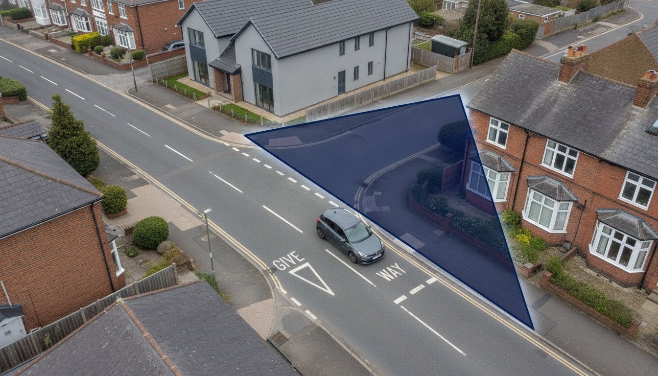
A restrictive site frontage doesn’t have to be the death knell for your development’s access potential. Many developers treat visibility splays as rigid, immovable obstacles that eat into valuable developable land, but the reality is far more flexible. If you’ve faced objections from Highway Officers or felt overwhelmed by the conflicting requirements of the DMRB and Manual for Streets, you know that securing a junction visibility analysis for planning applications is often the most contentious part of the process. You likely feel the pressure of balancing rigorous safety standards with your project’s commercial viability.
This guide provides the technical clarity you need to master UK highway safety criteria and ensure your access design is planning-compliant. We’ll break down the 2026 regulatory landscape, including the latest updates to the consolidated Manual for Streets and the alphanumeric DMRB standards. You’ll learn how to use site-specific 85th percentile speed data to justify tighter splays, successfully validate your Transport Statement, and protect your project from costly delays. We move from initial speed assessments to final design execution, providing the precision required for a successful planning outcome.
Key Takeaways
- Identify whether your project requires Manual for Streets or DMRB standards to ensure your access design aligns with the correct road hierarchy and speed.
- Understand how a professional junction visibility analysis for planning applications secures validation for your Transport Statement and mitigates safety objections.
- Learn how to precisely calculate X and Y distances to minimize unnecessary land take while maintaining essential Stopping Sight Distance requirements.
- Resolve land-take constraints by using site-specific 85th percentile speed surveys to justify visibility splays that work within your existing site boundaries.
- Strengthen your planning submission by integrating visibility splays with Swept Path Analysis to create a robust and technically compliant access strategy.
What is Junction Visibility Analysis in Transport Planning?
A Visibility Splay is the unobstructed area a driver needs to see traffic. In the context of highway engineering and the Geometric design of roads, this analysis ensures that any new access point doesn’t compromise public safety. A junction visibility analysis for planning applications is a mandatory technical assessment used to prove that drivers emerging from a site can see, and be seen by, approaching vehicles in time to avoid a collision. It’s the “eye-to-object” envelope that defines whether a site access is safe or a potential hazard.
Planning Officers and Highway Engineers prioritize this because safety is a non-negotiable statutory requirement. If a developer cannot demonstrate adequate visibility, the application fails the “safe and suitable access” test set out in the National Planning Policy Framework (NPPF). It isn’t just about looking left and right; it’s about the technical envelope required for safe interaction between all road users, including pedestrians and cyclists. Precision in these drawings is essential for securing a recommendation for approval.
There’s a direct mathematical relationship between vehicle speed and the physical space required to stop. As speeds increase, the distance a vehicle travels during the driver’s perception-reaction time and the subsequent braking phase grows. This total distance forms the basis of the visibility splay’s “Y-distance.” Accurate data is the only way to satisfy a Highway Officer’s scrutiny, especially when site constraints are tight.
The Consequences of Poor Visibility Design
Designing an access with substandard visibility leads to immediate friction with the Local Highway Authority. This often results in a “holding objection,” which halts the planning process until you provide a compliant solution. Beyond the regulatory hurdle, poor design increases the real-world risk of “failure to look” accidents. These incidents occur when the physical layout prevents a driver from seeing a hazard in time to react. If your site has limited frontage, failing to address these visibility constraints early can compromise the entire project’s viability and safety rating.
Visibility Splays vs. Stopping Sight Distances (SSD)
Stopping Sight Distance (SSD) is the physical distance a vehicle travels from the moment a driver identifies a hazard to the moment the vehicle stops. This calculation is the technical foundation of every junction visibility analysis for planning applications. While junction visibility focuses on the “eye-to-object” envelope at an intersection, forward visibility refers to the sightlines required on bends or crests to ensure drivers can see stationary hazards ahead. Both are essential components of a robust Transport Statement. Using site-specific speed data ensures these distances are accurate, preventing the over-provision of visibility that wastes developable land.
The Technical Anatomy of a Visibility Splay: X, Y, and Z Distances
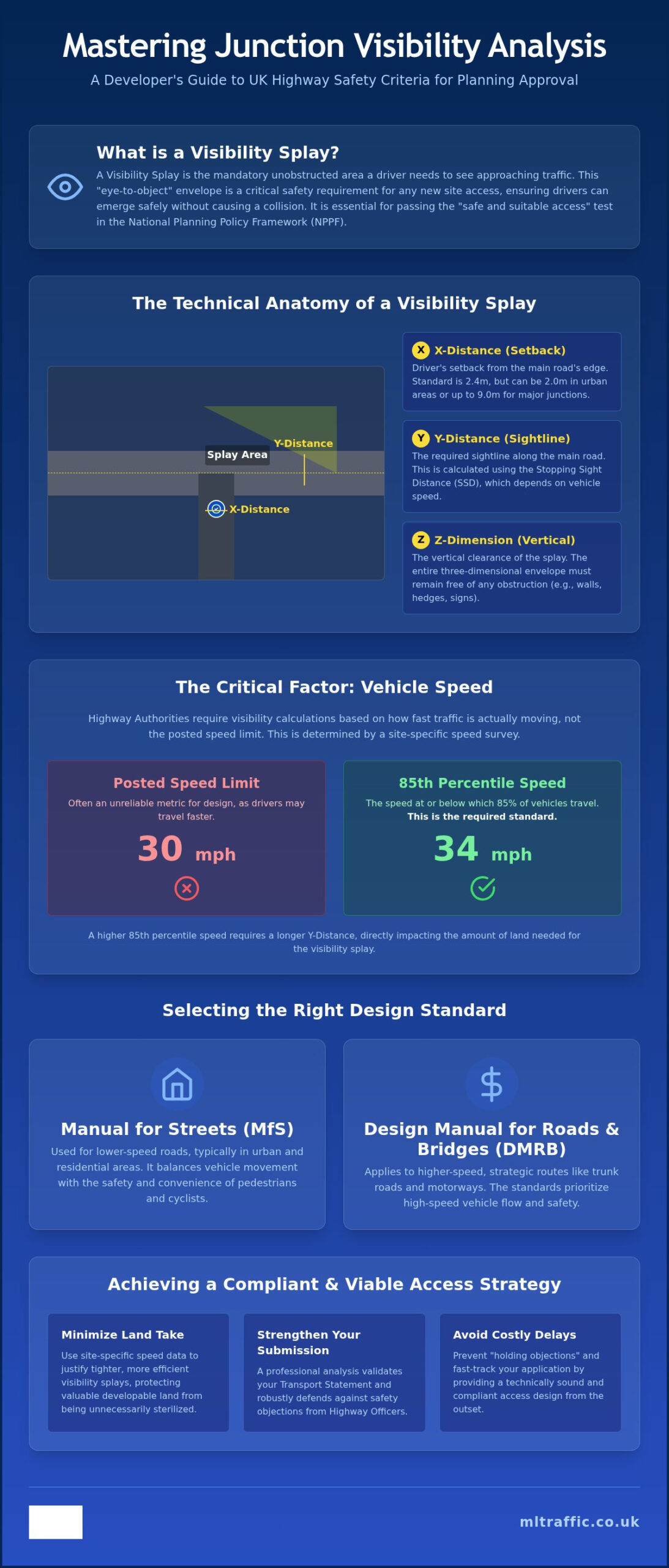
A visibility splay is a three-dimensional envelope that must remain clear of obstructions to ensure safe passage for all road users. The “X” distance represents the driver’s position, measured from the edge of the running carriageway back into the minor arm of the junction. While 2.4 meters is the standard setback for most residential developments, major junctions under DMRB guidelines may require 4.5 meters or even 9.0 meters. In constrained urban environments, a reduced 2.0 meter “X” distance is sometimes defensible. The “Y” distance extends from the junction along the main road, representing the sightline needed to see oncoming traffic. These two dimensions, paired with the vertical “Z” dimension, create the geometric footprint that Highway Officers scrutinize during a junction visibility analysis for planning applications.
Calculating the Y-Distance Correctly
The Y-distance is frequently the most contested element in a planning submission. It’s determined by the Stopping Sight Distance (SSD), which is the total distance a vehicle travels before coming to a complete stop. Instead of relying on the posted speed limit, Highway Authorities require the 85th percentile speed, the speed at or below which 85% of vehicles are observed to travel under free-flowing conditions. If a speed survey reveals traffic is moving faster than the limit, the required Y-distance will increase. You must also adjust these calculations for road gradients; downhill slopes significantly extend braking distances. Ongoing CIHT Visibility Research continues to refine how these distances are applied to balance driver safety with the needs of pedestrians and cyclists.
Eye and Object Heights (The Z-Dimension)
The “Z” dimension ensures that visibility isn’t just a flat line on a map but a functional clear zone. For car drivers, the standard eye height is between 1.05m and 2.0m above the road surface. However, if your development serves HGVs, the eye height increases to 2.0m, which can actually improve visibility over certain obstacles. The object height is equally vital; the splay must provide a clear view of objects as low as 0.6m, such as children or cyclists. To satisfy planning requirements, architects should provide section drawings that clearly show a hatched “clear zone” between these heights. This demonstrates that no walls, fences, or landscaping will block the critical line of sight. Ensuring these technical details are correct from the start helps in the successful validation of Transport Statements and avoids costly redesigns.
MfS vs. DMRB: Selecting the Right Visibility Standards
Selecting the correct technical standard is the most critical step in a junction visibility analysis for planning applications. The choice between Manual for Streets (MfS) and the Design Manual for Roads and Bridges (DMRB) dictates the scale of your visibility splays and, ultimately, the amount of developable land you retain. Using the wrong standard doesn’t just result in a request for more information; it often leads to an automatic planning refusal. This happens because Highway Officers view the misapplication of standards as a failure to recognize the functional nature of the road. While MfS supports urban and residential environments, DMRB is a rigorous framework intended for the strategic road network. Navigating the grey area at the 40mph threshold requires precise data rather than assumptions.
When to Apply Manual for Streets (MfS)
Manual for Streets (MfS) is the primary guidance for roads where measured speeds are 37mph (60kph) or lower. It shifts the design focus from “movement”, the rapid flow of vehicles, to “place”, which considers the needs of residents, pedestrians, and cyclists. The benefits of MfS are significant for developers. It permits shorter Y-distances and more flexible X-distances, such as the 2.0m setback often used in constrained urban settings. A new consolidated version of MfS is currently in final development, with a draft circulated in April 2026. This update reinforces the mandate to design safer, more accessible streets that don’t prioritize vehicle speed at the expense of site viability.
Challenging DMRB Requirements
Challenging a Highway Officer’s demand for DMRB standards is possible when you have the right evidence. Many authorities default to DMRB for any road with a 40mph limit, but this isn’t always appropriate for non-trunk roads that function as urban streets. Your secret weapon is the speed survey. By deploying Automatic Traffic Counters (ATC), you can prove the 85th percentile speed is actually below the 37mph threshold. This data allows you to apply MfS principles even on higher-speed roads, potentially saving meters of site frontage. When you combine this data-driven justification with Swept Path Analysis, you provide a comprehensive technical package that is difficult for authorities to ignore. This level of precision is exactly what’s needed to secure approval for complex access designs.
Common Constraints: Third-Party Land, Topography, and Vegetation
Securing a junction visibility analysis for planning applications often reveals physical or legal barriers that a simple site plan cannot resolve. One of the most significant hurdles is the “Blue Land” vs. “Red Land” dilemma. If your required visibility splay crosses land outside your ownership (Blue Land), the Highway Authority will likely object unless you can secure a legal agreement with the neighbor or prove the land is part of the public highway. For land already within the highway boundary, a Section 278 agreement is the standard mechanism to secure the right to clear obstructions and maintain sightlines in perpetuity.
Physical obstructions like bridge abutments, telegraph poles, or existing buildings create permanent blind spots that geometric design cannot always bypass. Topography also plays a critical role. If the main road is significantly higher or lower than your site access, the vertical curve (crest or sag) might block the driver’s view even if the horizontal splay looks perfect on paper. Technical standards require the triangular visibility zone to remain clear of all obstructions between 0.6m and 2.0m above the road level to ensure inter-visibility between drivers and vulnerable road users. This three-dimensional clearance is a non-negotiable foundation of a safe access design.
Managing Vegetation and Landscaping
Vegetation is a dynamic constraint that requires a lifetime management plan. Planning conditions typically mandate that visibility splays remain clear of any growth exceeding 0.6m in height. This creates a conflict when protected trees or established hedgerows sit within the splay. In these cases, you might need to negotiate a specialized maintenance strategy or, if safety is compromised, consider a slight shift in the access location. Highway Officers won’t accept “seasonal maintenance” as a solution; the splay must be clear 365 days a year to meet safety criteria. If a protected tree is the issue, early engagement with an arboriculturist is necessary to balance ecological preservation with highway safety.
Urban Constraints and “Zero Splay” Realities
In dense environments, such as central London, providing a traditional visibility splay is often impossible due to the proximity of neighboring buildings. These “zero splay” scenarios require a bespoke approach to safety. While some developers suggest using mirrors or “Stop” signs to mitigate poor sightlines, most Councils strongly dislike these measures due to maintenance and liability issues. Instead, you must demonstrate that the low vehicle speeds and high pedestrian activity justify a deviation from standard splay dimensions. For projects in high-density areas, Understanding Transport Assessment London is essential to navigating these intricate regional regulations. If you’re facing land ownership constraints or technical objections, our team can provide the precise Transport Statements and visibility analysis needed to move your application forward.
Integrating Visibility Analysis into Your Transport Statement
A junction visibility analysis for planning applications is the technical anchor of any successful Transport Statement. It provides the empirical evidence required to satisfy the “Safe and Suitable Access” mandate within the National Planning Policy Framework (NPPF). Without this data, your application lacks the necessary proof that drivers can interact safely with the existing highway network. A professional analysis doesn’t just show a triangle on a map; it demonstrates a deep understanding of driver behavior and vehicle mechanics. Integrating this early in your project lifecycle prevents the need for reactive design changes that often shrink developable site areas.
To provide a truly robust technical package, you must combine visibility splays with Swept Path Analysis. While visibility ensures a driver can see oncoming hazards, Swept Path Analysis proves that the vehicle can physically complete the turn without overrunning curbs or encroaching on opposing lanes. Highway Officers look for this synergy to confirm that the proposed access is functional in the real world. When these two assessments align, they create a compelling safety case that streamlines the negotiation process with Local Highway Authorities.
The Data Collection Phase
Reliable visibility splays start with high-quality data. Relying on the posted speed limit is a common mistake that leads to planning objections; Highway Officers know that actual vehicle speeds often differ from the signs. We use Automatic Traffic Counters (ATC) to collect 24/7 speed data over a full week. This provides a precise 85th percentile speed, which is the industry standard for determining Y-distances. Using accurate, site-specific data often allows us to justify shorter visibility splays than the default standards might suggest, potentially saving significant land at the site frontage.
Securing Professional Support
ML Traffic Engineers reduces the regulatory pressure on developers by providing precise engineering and expert negotiation. We handle the entire project lifecycle, from the initial traffic survey to the final technical report. This fully-managed approach ensures that your junction visibility analysis for planning applications is accurate, compliant, and ready for scrutiny. Our experts understand the intricate regional regulations across England, allowing you to focus on the broader development while we manage the highway safety criteria. You can Request a Transport Statement quote to secure the technical support needed for your submission.
Before submitting your application, ensure your visibility drawings include the following elements:
- Clear Scaling: Drawings should be at 1:500 or 1:200 for clarity.
- Labeled Distances: Both X and Y distances must be clearly marked and measured from the correct points.
- Data Citations: State whether the splay is based on MfS or DMRB and cite the speed survey source.
- Vertical Clearance: Indicate that the zone between 0.6m and 2.0m will remain unobstructed.
- Site Context: Include existing site boundaries and any permanent physical constraints.
Securing Your Planning Approval with Technical Precision
Mastering the technical requirements of visibility splays is the most effective way to protect your development from costly highway objections. By utilizing site-specific 85th percentile speed data, you can move away from restrictive speed limit assumptions and justify splay dimensions that maximize your site’s developable potential. Selecting the correct design standard, whether Manual for Streets or DMRB, ensures your access strategy aligns with UK safety criteria and specific regional expectations. Integrating a junction visibility analysis for planning applications with other technical assessments like Swept Path Analysis provides the comprehensive evidence Highway Officers require for validation.
ML Traffic Engineers UK provides expert analysis for UK planning applications. We are specialists in Transport Statements and Assessments, providing reliable data collection including Speed and Parking Surveys to reduce your regulatory pressure. Our team manages the full project lifecycle to ensure your technical drawings and reports are planning-ready. Contact ML Traffic Engineers UK for a professional Visibility Analysis to ensure your project meets the highest safety standards. We are ready to help you navigate these intricate regulations and secure a safe, compliant access design for your next development.
Frequently Asked Questions
What is the minimum visibility splay for a 30mph road?
The standard visibility splay for a road with a 30mph speed limit is typically 2.4 meters for the X-distance and 43 meters for the Y-distance under Manual for Streets (MfS) guidance. This Y-distance is based on the Stopping Sight Distance (SSD) for vehicles traveling at that speed. If a speed survey proves that the 85th percentile speed is lower than 30mph, we can often justify a reduced Y-distance to maximize your site’s frontage.
Can a visibility splay cross over a neighbour’s driveway or garden?
A visibility splay can physically cross third-party land, but it must be legally secured to remain unobstructed in perpetuity. If the splay crosses a neighbor’s garden, you generally need a legal agreement or an easement to ensure they don’t plant hedges or build walls that block the view. Highway Officers usually prefer splays to be contained within the site’s “Red Line” boundary or within the existing public highway to avoid enforcement complications.
What happens if I cannot achieve the required visibility splay?
Failing to achieve the required splay often results in a holding objection from the Local Highway Authority. You might need to relocate the access point, reduce the number of units to lower traffic intensity, or use a speed survey to justify a shorter splay based on actual traffic speeds. Professional junction visibility analysis for planning applications often identifies these constraints early, allowing for technical solutions like Section 278 agreements to clear highway land.
Is a speed survey always required for junction visibility analysis?
A speed survey isn’t strictly mandatory if you’re willing to design to the full standard of the posted speed limit. However, we highly recommend them for most developments. Using Automatic Traffic Counters (ATC) to gather 24/7 data allows us to use the actual 85th percentile speed rather than a generic limit. This often results in shorter required Y-distances, which can be the difference between a viable project and a planning refusal.
What is the difference between X and Y distances in planning?
The X-distance is the setback from the edge of the main road, representing the driver’s eye position before emerging. In residential settings, this is usually 2.4 meters. The Y-distance is the length of the sightline measured along the main road in both directions. Together, these dimensions define the visibility triangle. Getting these measurements right is a critical component of a junction visibility analysis for planning applications to ensure the access point is safe for all road users.
Do I need visibility splays for a private driveway application?
Yes, even a single private driveway requires adequate visibility splays to ensure safe entry and exit. While the requirements might be less stringent than for a major housing estate, the Local Highway Authority still applies Manual for Streets criteria to prevent “failure to look” accidents. Providing a clear technical drawing that shows these splays helps avoid delays during the validation of your planning submission and demonstrates a commitment to local road safety.
How does Manual for Streets affect visibility requirements in 2026?
The 2026 consolidated update to Manual for Streets (MfS) reinforces the shift toward people-centric street design. It provides practitioners with a stronger mandate to prioritize pedestrians and cyclists over high vehicle speeds in urban environments. This update encourages more flexible visibility requirements in low-speed areas, allowing for designs that better integrate with the local character. We use these latest standards to help developers create compliant, high-quality schemes that meet modern highway safety benchmarks.
Can I use a mirror to solve a visibility problem for my planning application?
Local Highway Authorities almost never accept traffic mirrors as a primary solution for poor visibility. Mirrors are prone to vandalism, weather obscuration, and can distort a driver’s perception of speed and distance. Relying on a mirror creates a long-term maintenance liability that Councils are unwilling to accept. Instead, you should focus on technical engineering solutions, such as speed reduction measures or adjusting the access geometry, to achieve a safe and compliant visibility splay.

Disclaimer
The content on mltraffic.co.uk, including all technical articles, guides, and resources, is provided for general informational and educational purposes only. It is not intended to constitute professional advice in traffic engineering, transportation planning, development approvals, or any other technical or legal field.
While ML Traffic Engineers makes every reasonable effort to ensure the accuracy, completeness, and timeliness of the information published, we do not provide any warranties or representations (express or implied) regarding its reliability, suitability, or availability for any particular purpose. Any reliance you place on the content is strictly at your own risk.
In no event shall ML Traffic Engineers, its directors, employees, authors, or affiliates be liable for any direct, indirect, incidental, special, consequential, or punitive damages (including, without limitation, loss of profits, data, or business opportunities) arising out of or in connection with the use of, or inability to use, any information provided on this website.
The articles and guides on this site are not a substitute for engaging a qualified, professional traffic engineer to assess your specific project requirements. For tailored advice, compliance assessments, or traffic engineering services, please contact a competent professional.
This disclaimer may be updated from time to time without notice. By accessing or using this website, you agree to be bound by the most current version of this disclaimer.