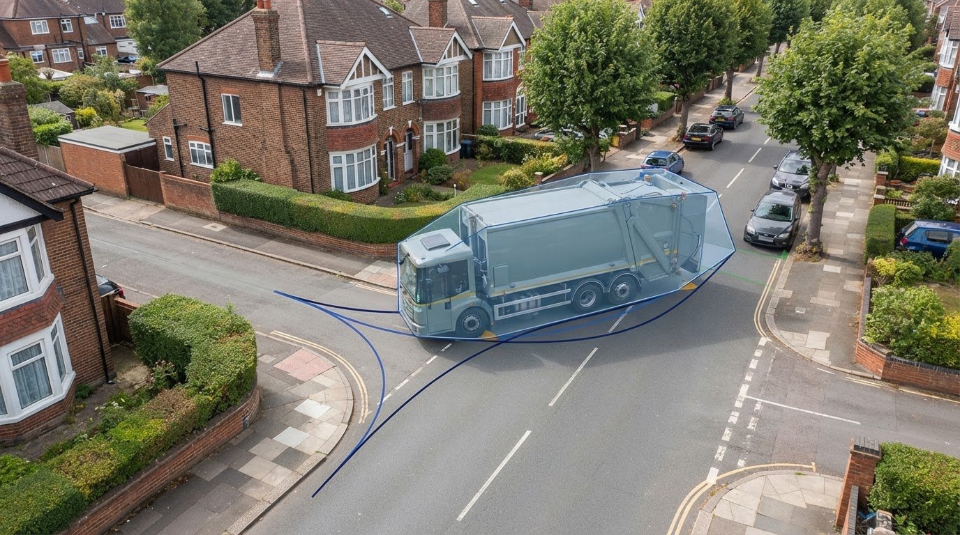
A residential road can look wide enough on a plan yet leave a refuse lorry unable to turn. Swept path analysis for residential access roads models how selected vehicles move through roads, junctions and turning areas, including wheel paths and body overhang. It shows whether vehicles can enter, manoeuvre and exit without conflicting with kerbs, obstacles or pedestrian space.
Checking road width alone may not reveal whether a layout will work. As a vehicle turns, its rear wheels follow a tighter arc than its front wheels, so the full movement matters. Councils may require swept path analysis for a planning application, particularly where access is constrained or larger vehicles need to use the development.
This guide explains what swept path analysis assesses and how it can inform residential road and junction layouts. It covers which vehicle movements may need modelling, how the results can reveal design constraints, and why those findings matter before construction begins.
Key Takeaways
- Vehicle tracking checks the space a vehicle needs to turn, including wheel paths and body overhang, against roads, kerbs and obstacles.
- Select vehicles that reflect the development’s likely users, such as refuse lorries, emergency vehicles, delivery vans and cars.
- Use vehicle movements to assess whether access points, junctions, turning areas and parking layouts work together safely.
- There is no single road width or junction radius that suits every layout; vehicle size, turning movements and site constraints shape the design.
- Early analysis can reveal where a layout may need adjustment and provide evidence for planning discussions with the highway authority.
What is Swept Path Analysis?
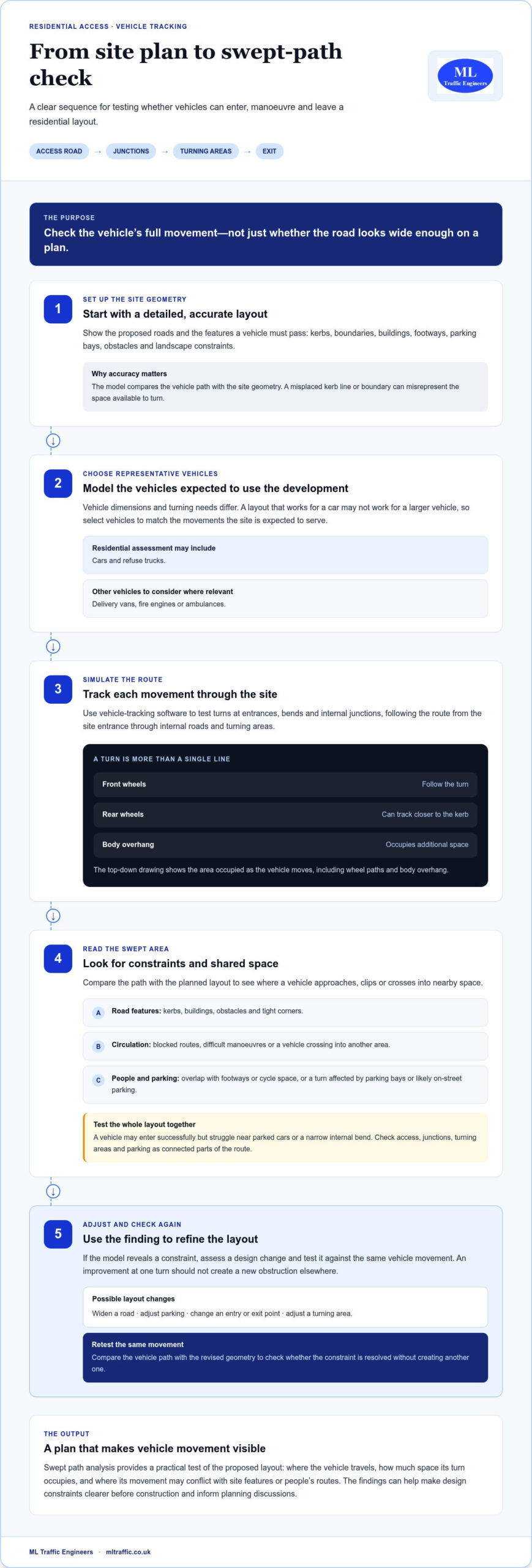
Swept path analysis models a vehicle’s movement through a site, showing the space it needs to turn. Vehicle-tracking software tests the movement against the proposed layout, including access roads, kerbs and obstacles.
Vehicle Tracking for Site Access
Vehicle tracking maps a selected vehicle’s route across a site, from the entrance through internal roads and turning areas. A route that looks clear on a plan may not leave enough room for the vehicle’s full turning movement. A top-down drawing shows wheel paths and body overhang, helping identify where the vehicle approaches kerbs, buildings or other constraints.
The software models vehicle dimensions, turning radius, site layout and movement characteristics. The result shows the area occupied as the vehicle moves, including the additional space needed around corners. For example, a refuse vehicle’s front wheels may clear a bend while its rear wheels track closer to the kerb. The drawing makes this difference visible before construction.
Vehicle Selection and Turning Movements
Vehicle selection means choosing representative vehicles for the movements expected at a residential development. The choice matters because a layout that accommodates cars may not work for a refuse lorry, delivery van or emergency vehicle. Modelling the relevant vehicles lets designers assess access and circulation against the site geometry, rather than assuming every vehicle follows the same path.
Tracking software simulates each vehicle’s turns at entrances, bends and internal junctions. A residential assessment may include cars and refuse trucks; other developments may need vans, fire engines or ambulances considered. The output helps identify tight corners, blocked routes and manoeuvres that require vehicles to cross into another area.
That crossing can affect more than vehicle access. If a vehicle’s swept area overlaps a footway or cycle space, the plan can reveal a potential conflict with pedestrians or cyclists. Designers can then consider layout changes, such as adjusting a turning area or parking arrangement. The assessment shows where vehicle movements and people’s routes occupy the same space.
A residential access road may serve several vehicle types, each with different dimensions and turning needs. Checking only a passenger car could miss constraints for a refuse vehicle entering, turning and leaving. Comparing vehicle paths helps show whether the layout supports expected movements while accounting for kerbs, parked vehicles and pedestrian space. The model is a practical test of the plan, not just a line showing where a vehicle travels.
Residential access and road layouts
A residential layout must accommodate vehicle movements around the features shown on its plan. Swept path analysis tests how the proposed access road, internal routes, junctions and parking areas work together, helping identify constraints before construction. For example, a vehicle may enter successfully but struggle to turn near parked cars or a narrow internal bend.
Mapping accuracy matters because the vehicle path is compared with the site’s geometry. The analysis needs a detailed layout showing roads, kerbs, obstacles and other key features. Ordnance Survey maps provide detailed mapping for planning and development, while project drawings can show the proposed arrangement. If a kerb line or boundary is misplaced, the model may not represent the space available for a turn.
CAD layouts can provide the geometry needed to assess proposed roads and parking. They allow vehicle paths to be compared directly with building edges, footways, parking bays and landscape constraints. A turning path that clips a parking bay, for instance, may show that the arrangement obstructs access or limits circulation. The drawing should make both the movement and nearby site features clear.
Parking accessibility depends on how vehicles enter, leave and pass through spaces. Tracking can test whether a car can reach a bay without obstructing an internal route and whether larger vehicles can navigate nearby turns. The assessment should also account for planned or likely on-street parking, which can reduce usable road space.
When a model reveals a constraint, designers can assess whether a layout change resolves it. Options may include widening a road, adjusting parking or changing an entry or exit point. Test the change against the same vehicle movement, so an improvement to one turn does not create a new obstruction elsewhere. This comparison informs design discussions before construction begins.
For planning discussions, a proposed layout can be considered alongside the buildings and development boundaries, as well as highway engineering requirements such as road widths and bend radii. Project teams can review vehicle paths against the proposed geometry using this guide to swept path analysis, helping make layout constraints clearer before an application is submitted.
Residential access roads and junctions
Residential roads must support the turns vehicles make at bends, junctions and site entrances. Vehicle tracking tests those movements against the proposed layout, including the space needed to enter, turn and leave safely. A route that works for a car may create a different challenge for a refuse lorry, particularly where a narrow road meets a sharp bend.
Bends, Junctions and Roundabouts
A bend, junction or roundabout changes a vehicle’s direction and the space its movement occupies. Tracking shows whether the selected vehicle can follow the route without its wheels or body overhang striking kerbs, obstacles or nearby features. This matters when a large vehicle needs to use more of the carriageway to negotiate a turn.
Consider a refuse lorry approaching a bend near a junction. Its rear wheels may track closer to the kerb while its body takes a wider path. Forward visibility to bends, including at junctions, also matters when large vehicles use the full carriageway width to manoeuvre on narrow roads. The drawing helps designers assess the movement alongside available sightlines.
Access Junction Manoeuvres
At an access junction, vehicles turn between the public highway and a development’s internal road. Tracking can test entry and exit movements, showing whether a vehicle can negotiate the junction without conflicting with the road edge or other site features. This helps demonstrate how the proposed access supports safe movement to and from the highway.
The direction of travel matters. A vehicle turning into a site may need a different path from one leaving, especially where the entrance meets a narrow road or sits close to a bend. Assessing both movements can reveal a layout that accommodates entry but makes exit difficult. The plan can show where the vehicle path approaches kerbs or requires additional manoeuvring space.
Road Widths and Turning Areas
Road width, junction radius and turning-area geometry determine how much room a vehicle has to complete a manoeuvre. Analysis tests these features against the vehicles expected to use the development. Refuse vehicles that are 11.2m long are one example considered in local guidance for turning-head assessments; some local authorities use larger vehicles.
Refuse and recycling vehicles can influence cul-de-sac geometry and hammerhead design because their turning needs affect usable space. Checking swept-path widths and bend radii helps establish whether expected vehicles can manoeuvre without overrunning kerbs. A constrained turning head may need a revised shape or road arrangement to accommodate the intended movement.
There is no single width or radius that suits every residential road. Vehicle dimensions, approach direction, surrounding kerbs and the intended movement all affect the space required. Testing these factors together shows whether the proposed geometry supports the manoeuvre, rather than relying on road width alone.
What swept path analysis assesses
Swept path analysis assesses the space a chosen vehicle needs throughout a movement, not just at its starting point or destination. A drawing can show front and rear wheel paths alongside the vehicle body’s overhang. For example, a van may clear a corner with its front wheels while its rear body approaches a wall or kerb. The complete movement shows whether the route fits the layout.
Vehicle movements are tested against the site’s roads, junctions, parking areas and other fixed features. A tracking drawing can assess cars, delivery vans, refuse vehicles and HGVs, each with its own dimensions and turning characteristics. Comparing paths helps show whether the layout works for the vehicles expected to enter, circulate through and leave the development.
The assessment also identifies constraints along the route. A tight corner, parked car, projecting wall or narrow entrance can restrict a turning movement. For instance, a refuse vehicle may need more room at an internal junction than a car. The plan can show where its path approaches an obstruction, helping architects and designers identify which part of the layout needs attention.
Parking is another key test. Tracking can assess whether a vehicle can enter or leave a space without striking an adjacent bay, blocking circulation or crossing into a conflicting route. A car reversing from a bay may need to turn across an internal road. Modelling that movement alongside delivery or refuse access helps reveal competing demands in the same area.
Vehicle paths can also be compared with pedestrian and cycle space. If a vehicle’s swept area overlaps a footway, cycle route or waiting area, the drawing reveals a potential conflict. For example, a large vehicle may need to use more of the carriageway while negotiating a bend. The result gives the design team a clearer view of where people and vehicle movements intersect.
The output should make vehicle paths visible and identify potential problems, such as tight corners or obstructions. It can inform specific design decisions: whether to adjust parking, revise a junction or change an access arrangement. Architects and transport planners can use the drawing to consider how one change affects other movements. A wider turning area might help a refuse vehicle, but the revised layout must still account for parking and pedestrian space.
The practical takeaway is that swept path analysis tests movement against the whole design, not just a road-width measurement. A useful assessment links each selected vehicle to its route and shows where its wheels and body travel. This evidence helps the project team distinguish a workable layout from one that creates conflicts, while identifying the location and movement that need further design attention.
What minimum road widths, junction radii and turning areas are required for residential access roads?
There is no single road width or junction radius that suits every residential layout. The required space depends on the vehicles expected to use the road, their turning movements and the site geometry. Swept path analysis tests these factors together, showing whether a vehicle can manoeuvre without overrunning kerbs or encountering an obstruction.
Vehicle choice is central to the assessment. Refuse and recycling vehicles are among the largest vehicles that regularly access residential areas, so their movements can influence road widths, cul-de-sac geometry and hammerhead design. Check bend radii and swept-path widths against the vehicles expected to use the road. A measurement alone cannot show whether a vehicle can complete a particular turn.
Where a development needs to accommodate heavy goods vehicles, the design vehicle’s dimensions must inform the assessment. For example, modelling a long HGV can reveal how its length and turning movement interact with the proposed road, junction and turning area. The analysis should reflect the vehicles the development is expected to serve, rather than treating one vehicle size as a universal road-width standard.
Turning heads need particular attention because vehicles must change direction within a defined space. A hammerhead that accommodates a car may not provide a suitable movement for a refuse vehicle. The assessment compares the selected vehicle’s path with the turning area and its kerbs. If the route overruns the edge, designers can review the geometry and test a revised arrangement.
Junction radii should be considered alongside the approach road and available visibility. Assess road widths and bend radii against the planned layout, including development boundaries and buildings that constrain the available space. This helps designers understand how vehicle movements fit the whole site, rather than treating a radius as an isolated figure.
Parking and other constraints can change the usable space. A road may appear wide enough on an unobstructed plan, but planned or likely on-street parking can affect vehicle movement. Account for that parking alongside kerbs, obstacles and the vehicle’s approach direction when reviewing a proposed width or turning area.
The useful result is evidence that the expected vehicle can complete its movement within the proposed layout, not a generic minimum. Compare each vehicle path with the road geometry and identify where it approaches a kerb, obstacle or parking area. This gives the design team a clear basis for reviewing the width, radius or turning space needed for the specific movement.
ML Traffic Engineers UK: Transport Statements
ML Traffic Engineers UK provides Swept Path Analysis for assessing vehicle movements in residential access layouts and planning applications. Use the service when a proposed road, junction or turning area needs to be assessed against the vehicles expected to use it. If an application also needs transport planning documentation, a Transport Statement or Transport Assessment can address the development’s transport implications. Parking Surveys can provide relevant parking information for project assessments.
The appropriate documentation depends on the development and the planning question it needs to address. ML Traffic Engineers UK provides transport planning and traffic engineering support for project teams preparing evidence for planning applications.
Contact ML Traffic Engineers UK to discuss your project’s transport planning requirements, or visit mltraffic.co.uk.
Move your residential layout towards planning readiness
The next step is to align the proposed layout with the transport evidence your planning application needs. An assessment early in design can help the project team focus on practical questions, such as which vehicle movements need review and how parking information supports the wider application. Swept path analysis for residential access roads can form part of that evidence, alongside the transport documentation relevant to the development.
ML Traffic Engineers UK provides Swept Path Analysis, Transport Statements and Parking Surveys. These services support different parts of a project’s transport planning, from reviewing vehicle movements to preparing information for planning. The right combination depends on the questions your scheme needs to address.
Take the next step by discussing your development’s transport requirements. A focused conversation can help you identify the evidence needed to progress the layout and prepare for planning discussions. With the transport considerations addressed clearly, your team can move forward with greater clarity and confidence.
Frequently Asked Questions
What is swept path analysis for residential access roads?
It is a vehicle movement assessment that tests whether selected vehicles can use a proposed residential route. The analysis considers the actual layout and each vehicle’s dimensions, including its length, width and turning radius. For example, a delivery van and a refuse vehicle may negotiate the same entrance differently. Comparing their paths helps identify which movement needs a design response before the layout advances.
What vehicle design standards and dimensions are used for residential access road swept path analysis in the UK?
Vehicle dimensions depend on the design vehicle chosen for the development and the movements it needs to make. The model uses details such as length, width and turning radius; applicable highway authority guidance also informs the assessment. For example, Leicestershire County Council requires analysis for 18.55m long HGVs where developments need to accommodate them. That is a vehicle length to model, not a standard road width.
How should refuse collection vehicles and fire appliances be included in residential access road analysis?
Include refuse vehicles and fire appliances where those vehicles need to reach or circulate through the development. Leicestershire County Council recommends including refuse lorries and fire tenders in swept-path checks. Its guidance requires analysis for refuse vehicles that are 11.2m long at turning heads, unless the local borough or district already uses a larger vehicle. Model each vehicle’s relevant route, including its approach to the site and turning movements.
What drawings and evidence should a swept path analysis report include for planning approval?
Provide a legible tracking drawing based on a detailed site layout, with the vehicle route shown against relevant roads, kerbs, obstacles and other features. The report should identify potential issues, such as a tight corner or obstruction, and make the assessed vehicle movement clear. The National Planning Policy Framework, paragraph 108, states that developments should provide safe and suitable site access for all users, giving access evidence clear planning relevance.
What are common swept path analysis failures and how can road layouts be redesigned to fix them?
Common issues include a vehicle path overrunning a kerb, a tight turn, an obstruction or a manoeuvre that conflicts with parking or pedestrian space. The response depends on where the movement fails. Designers may widen a road, alter the parking layout or modify an entry or exit point. Re-test the revised geometry against the same vehicle movement, then review whether the change affects other site routes.

Disclaimer
The content on mltraffic.co.uk, including all technical articles, guides, and resources, is provided for general informational and educational purposes only. It is not intended to constitute professional advice in traffic engineering, transportation planning, development approvals, or any other technical or legal field.
While ML Traffic Engineers makes every reasonable effort to ensure the accuracy, completeness, and timeliness of the information published, we do not provide any warranties or representations (express or implied) regarding its reliability, suitability, or availability for any particular purpose. Any reliance you place on the content is strictly at your own risk.
In no event shall ML Traffic Engineers, its directors, employees, authors, or affiliates be liable for any direct, indirect, incidental, special, consequential, or punitive damages (including, without limitation, loss of profits, data, or business opportunities) arising out of or in connection with the use of, or inability to use, any information provided on this website.
The articles and guides on this site are not a substitute for engaging a qualified, professional traffic engineer to assess your specific project requirements. For tailored advice, compliance assessments, or traffic engineering services, please contact a competent professional.
This disclaimer may be updated from time to time without notice. By accessing or using this website, you agree to be bound by the most current version of this disclaimer.