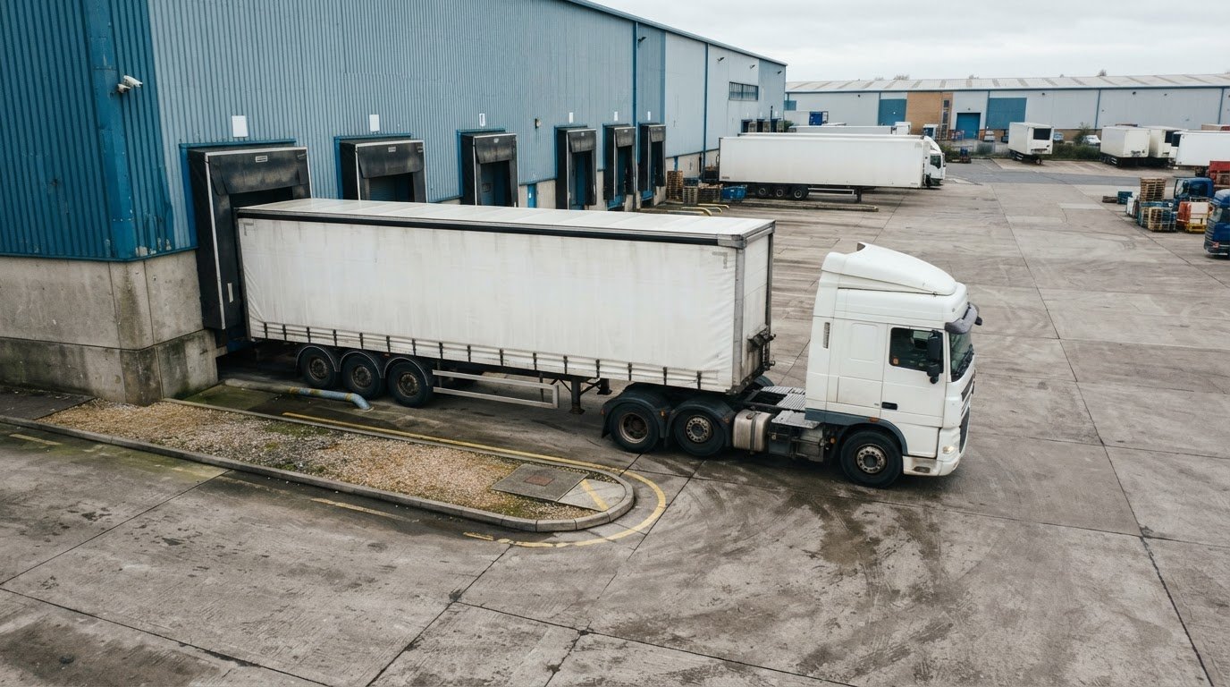
A depot layout can look workable on a plan yet leave a delivery vehicle unable to turn safely. Swept path analysis for a logistics depot models a selected vehicle’s movement and shows the space occupied by its wheels, body and overhang as it manoeuvres. This makes tight access routes, yard turns and loading areas easier to assess before construction.
The question is not simply whether a vehicle can enter the site. Turning routes, reversing manoeuvres, parking positions and dock access all affect how vehicles move through a depot without conflicting with kerbs, buildings or other fixed features.
This article explains what swept path analysis shows, how it helps coordinate parking and loading layouts, and what information is needed to assess a proposed manoeuvre. It also explains how early modelling can reveal access constraints while there is still time to adjust the design.
Key Takeaways
- Understand how swept path modelling shows the space a vehicle’s wheels, body and overhang need through a turn.
- See how testing vehicle movements can inform depot access, parking layouts and loading dock positions.
- Learn which layout details, vehicle dimensions and manoeuvres shape a useful assessment.
- Spot potential conflicts, tight turns and access constraints early enough to consider design changes before construction.
- Know why planning requirements can vary and what to establish for a depot’s specific application.
What Is Swept Path Analysis?
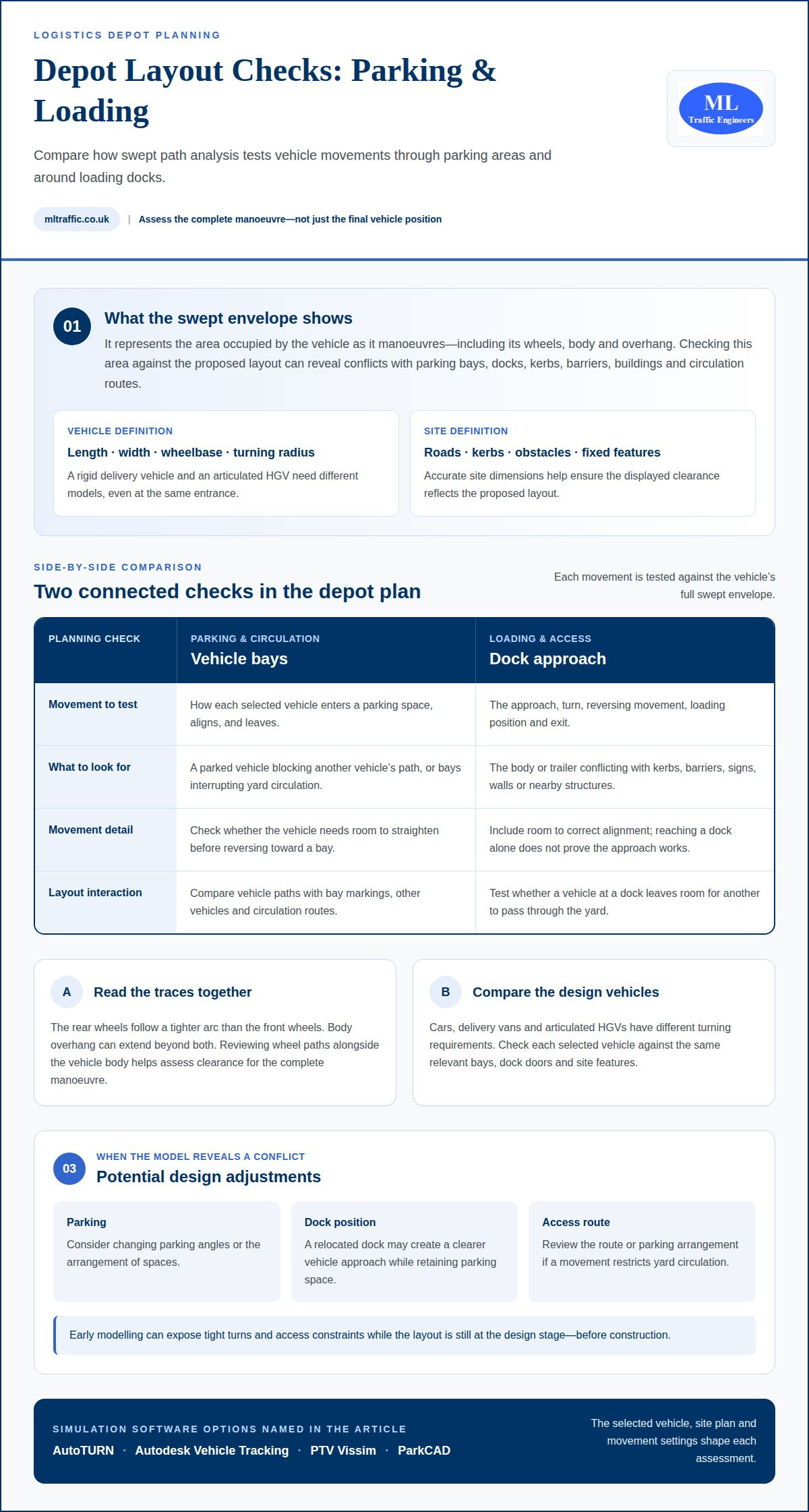
Swept path analysis models how a selected vehicle moves along a proposed route or through a space. It shows the area occupied during a manoeuvre, not just the tracks followed by the wheels. At a depot entrance, for example, the drawing can show whether the vehicle body or rear overhang reaches a kerb, barrier or building. This occupied area is called the swept envelope.
The model uses vehicle dimensions and site-layout information to represent a specific movement. Length, width, wheelbase and turning radius help define the vehicle; roads, kerbs, obstacles and other fixed features define its surroundings. The result is useful only if those inputs accurately represent the proposed depot and vehicle type. A rigid delivery vehicle and an articulated HGV need different models, even if they use the same entrance.
There are two broad ways to represent a vehicle’s swept path. Vehicle movement can be represented using different modelling approaches, depending on the manoeuvre being assessed. Both show the space swept by the whole vehicle. Dynamic modelling can represent a sequence of steering positions rather than relying on one fixed curve. This distinction matters when a depot route includes a tight turn, reversing or restricted clearance.
CAD-based and browser-based software
CAD-based workflows plot vehicle movements against a digital site plan. Static swept-path templates can be imported into planning tools as DXF or DWG files, allowing the vehicle envelope to be reviewed alongside roads, parking spaces and dock positions. Keep site dimensions consistent so the apparent vehicle clearance reflects the proposed layout, not a scale mismatch.
Browser-based tools offer another way to model swept paths through a web interface. The core assessment questions are the same: which vehicle is represented, what manoeuvre is being tested, and which site features constrain it? Before relying on a browser-based output, the project team needs to understand the tool’s vehicle library, input requirements and drawing outputs. These determine whether it suits a planning drawing or an early layout review.
Simulation software options
Software used for swept-path simulation includes AutoTURN, Autodesk Vehicle Tracking, PTV Vissim and ParkCAD. These are options, not interchangeable results: the selected vehicle, site plan and movement settings shape each assessment. A useful sequence is to select the design vehicle, define the entry, turn or exit, then review the full swept envelope against obstacles.
The final drawing should show the tested movement clearly against the relevant highway or depot layout. Reviewing wheel paths alongside the vehicle body can reveal different clearance issues. A vehicle’s rear wheels follow a tighter arc than its front wheels, while body overhang may extend beyond both. Reviewing these traces together helps planners assess whether the proposed spaces accommodate the complete manoeuvre.
Space optimisation for parking and loading docks
At a logistics hub, parking bays, circulation routes and loading docks all compete for space. Assessing vehicle movements across the proposed layout helps show how these functions can work together.
Parking and Loading Area Layouts
Start by simulating how each selected vehicle enters a parking space, aligns with a loading dock and leaves. The drawing can reveal whether a parked vehicle blocks another vehicle’s path or interrupts yard traffic. For example, relocating a dock may create a clearer approach while retaining space for parking.
Review the whole movement, not just the final position. A delivery vehicle may need room to straighten before reversing towards a bay, while other vehicles continue through the site. Testing these movements against the proposed parking layout helps identify conflicts between waiting vehicles, dock access and circulation. It also shows whether parking spaces occupy useful manoeuvring areas.
To assess the layout, compare the swept envelopes of the design vehicles using each area. A car, delivery van and articulated HGV have different turning requirements. Their paths can be checked against bay markings, dock doors and one another. This can help planners adjust parking angles or dock positions while the layout is still at the design stage, rather than after construction.
Loading Area Site Constraints
Loading areas are often set within fixed site boundaries, so the assessment needs to account for features that cannot easily move. Kerbs, barriers, signs, walls and neighbouring structures can limit turning space. A simulated approach can show whether a vehicle’s body or trailer conflicts with these obstacles while entering, reversing or leaving a dock.
Assess the approach route and loading position together. A vehicle might reach a dock but need to cross an adjacent parking space or encroach on a circulation route to line up. The drawing should show the complete manoeuvre, including the space needed to correct alignment. This helps distinguish a workable loading position from one that only works in isolation.
Site constraints also affect how loading and parking interact during normal depot activity. A layout can be tested for a vehicle waiting at a dock while another passes through the yard. If the movement is restricted, planners can consider changes to the proposed dock position, access route or parking arrangement. Explore swept path assessment support when these movements need to be tested alongside depot parking and access planning.
Identifying access and turning problems before construction
Testing the proposed layout before construction helps reveal where vehicle movements may conflict with site features. A model can show whether an entrance, internal turn or loading approach gives the selected vehicle enough room to manoeuvre. Designers can then consider changes while access routes, kerbs and building positions are still part of the plan, rather than relying on adjustments after the depot is built.
Common errors include using the wrong vehicle dimensions, relying on an inaccurate layout, and omitting tail swing or trailer tracking. These omissions can hide tight turns, kerb overruns and potential collision points, creating planning concerns or unsafe movements.
Show pedestrians, cyclists, parked cars and neighbouring roads as relevant constraints in the layout being tested. Assess the vehicle path against footways, cycle routes, parking positions and highway edges to identify where turning could encroach on those spaces.
Accuracy starts with the inputs. Site plans need to represent road widths, kerbs, obstacles and boundaries clearly, and vehicle data needs to match the design vehicle. Length, width, wheelbase and turning radius affect the result. For an articulated vehicle, the trailer trajectory matters too; projecting loads or special steering behaviour may also change the space required.
Review the full manoeuvre, not only the entrance or final parking position. A vehicle may clear the access but need more room at an internal bend, reversing point or loading area. Swept path analysis helps identify these restrictions by showing the vehicle body and wheel paths alongside the proposed layout. Comparing them visually makes it easier to locate a conflict and consider a design response.
Possible responses include widening a route, changing an entry or exit point, or repositioning a fixed feature. The right adjustment depends on where the model shows restricted manoeuvrability and which parts of the layout can change. Testing the revised movement against the same vehicle and site constraints makes the design decision traceable.
Emergency access and unusual deliveries may need separate vehicle checks. A fire engine, ambulance or abnormal-load vehicle can have different dimensions and turning needs from routine depot traffic. Modelling each relevant vehicle on its route can reveal access constraints before construction, including turns that may conflict with kerbs, structures or the neighbouring highway.
Drawings should make the tested movement clear enough for a planning review. They can show the vehicle’s position through the manoeuvre, its swept envelope and nearby constraints. A swept path assessment drawing can help communicate where a layout works and where a change may be needed. Rechecking the revised design then confirms whether the specific access or turning issue has been addressed.
Swept path analysis for depot access and manoeuvring
Depot manoeuvres need to work within the proposed site and at its connection to the highway. The assessment should reflect the intended vehicle, route and planning application.
Planning Application Requirements
UK planning authorities may require swept path analysis for developments involving vehicle movements, including depots with access routes, loading bays or parking areas. The assessment helps demonstrate whether the proposed layout can accommodate the vehicles expected to use it. The relevant movements depend on the depot’s operation, such as entering and leaving, reaching a loading area, or turning within the yard.
For a planning application, make the tested vehicle and manoeuvre clear on the drawings. A plan might show an HGV entering from the highway, turning through the site and leaving in forward gear. Reviewing this route can reveal whether the layout needs adjusting before the application is submitted.
Planning Guidance and Highway Authority Requirements
There is no single swept-path requirement that applies in the same way to every UK depot. Planning and local highway authority expectations depend on the proposal, vehicle movements and site access being assessed. The relevant authority may require drawings to demonstrate that the selected design vehicle can use the access and internal layout safely.
Match the application drawings to the depot proposal, including any vehicle or manoeuvre specified for assessment. A drawing for routine deliveries may not demonstrate access for a larger vehicle if the authority expects that movement to be tested. Show the complete route under consideration, including its connection to the neighbouring highway.
Preparing the Analysis
Preparation starts with an accurate site or layout drawing and the vehicle type to be modelled. Define the movement too: for example, entering, turning at a yard head, reversing towards a loading area, or exiting. A plan in PDF or CAD format can provide the layout for the assessment.
Vehicle data should match the chosen design vehicle. Relevant dimensions include length, width, wheelbase and turning radius; an articulated combination also needs its trailer configuration represented. These inputs affect how the model tracks through a turn and the space required around the vehicle.
A practical preparation sequence is to define the manoeuvre, apply the vehicle dimensions to the site plan, then review the resulting path against kerbs, structures and other constraints. If a planning authority requests a specific vehicle, use that design vehicle or its confirmed dimensions. Show the vehicle body position, wheel paths and swept envelope alongside the layout.
This process helps demonstrate whether vehicles can access, turn within and leave the depot safely. It also gives the planning team a clear basis for considering changes to access geometry, turning space or parking layouts before construction. An appropriate assessment links each drawing to the application’s actual vehicle movements, rather than treating the site entrance as an isolated feature.
When is swept path analysis required for a UK logistics depot planning application?
UK local authorities often require swept path analysis for developments involving vehicle movements. A logistics depot may need it to show how vehicles use the site entrance, internal roads, loading bays and parking areas. The relevant movements depend on the proposed layout and the vehicles expected to visit. A drawing can help planning officers assess whether those vehicles can enter, manoeuvre and leave within the available space.
The need is clearest where larger vehicles use constrained access or make complex turns. For example, a depot beside a narrow highway may need to demonstrate how an HGV turns through its entrance without conflicting with kerbs or site boundaries. A layout with reversing near loading docks may also need assessment to show the vehicle’s route and any restricted manoeuvring areas.
Planning requirements depend on the application and the movements being assessed. A new access, internal road, loading bay or parking area can involve vehicle movements that need to be demonstrated. The planning or highway authority may identify the vehicles and manoeuvres relevant to its review. Include routine delivery routes and any specific movements the depot proposal needs to accommodate.
Make the relationship between the vehicle and the site easy to assess in the submission. A useful drawing identifies the modelled vehicle and shows its path against the proposed layout. For a depot, this could include a vehicle entering from the adjoining highway, reaching a loading area and exiting. If the layout changes, update the drawing to show the revised arrangement.
Planning teams should consider the route as a connected movement rather than treating each area separately. An entrance may accommodate a turn, while the same vehicle becomes constrained at an internal corner or parking area. Showing the route through to its destination can reveal where the design needs adjustment. This evidence helps explain how the proposal accommodates vehicle access and circulation before construction.
For a London application, establish which vehicles the depot is designed to serve and which movements need to be demonstrated. Use the corresponding vehicle dimensions and current site layout, including relevant highway and fixed site features. Where the authority requests a particular vehicle or manoeuvre, address that request directly. Clear, consistent drawings connect the proposed design with the movement being assessed.
Early assessment is useful when access, turning space or loading arrangements remain open to design changes. It can identify a constraint while the application layout can still be revised, rather than leaving it unresolved until construction. Arrange a depot access assessment to examine the vehicle movements relevant to your planning proposal.
ML Traffic Engineers UK: Swept Path Analysis
ML Traffic Engineers UK provides swept path analysis to assess depot access, turning movements and vehicle manoeuvring against a proposed layout. Use this service when a planning application needs drawings showing how specified vehicles can use entrances, internal routes or loading areas. The assessment can identify access constraints while the design can still be adjusted.
Where an application needs supporting transport documentation, Transport Statements and Transport Assessments can address relevant transport planning matters. Parking Surveys can provide parking data to inform a development assessment. Each service has a distinct role, depending on the planning question and evidence required.
For a depot proposal, share the site layout, design vehicle and manoeuvres to be assessed. Contact ML Traffic Engineers UK to discuss swept path analysis for your project.
Plan the next design decision
Use the next design stage to prepare a clear brief: define the depot’s operating vehicles, the movements the layout must support and the areas still open to change. This gives the project team a practical basis for coordinating access design with the planning application. Swept path analysis for a logistics depot can inform these decisions before the layout is fixed.
ML Traffic Engineers UK offers Swept Path Analysis alongside Transport Statements and Parking Surveys. These services can support projects where vehicle access, transport planning documentation or parking evidence needs consideration. The next step is to set out the site layout and the movements to be assessed.
Contact ML Traffic Engineers UK to discuss the assessment for your depot. A defined brief can help move the planning work forward with clarity.
Frequently Asked Questions
What Does the Final Drawing Show?
A final drawing shows the vehicle’s position, wheel paths and swept envelope against the site or highway layout. It can also clarify the direction and sequence of a manoeuvre, such as entering a yard before reversing towards a dock. This helps reviewers see where clearance is tight and which part of the route needs attention, rather than interpreting an isolated curve without its site context.
What Vehicles Can Be Assessed?
Assessments can cover passenger cars, vans, rigid delivery vehicles, refuse vehicles and construction vehicles, depending on the project. Depot work may also need to consider articulated HGVs, trailers, tankers or container carriers. Choose a vehicle that reflects the movement being tested. For example, a delivery van model does not demonstrate that an articulated lorry can complete the same turn.
Why are swept paths important?
Swept paths help show whether a vehicle’s complete movement fits within the available route and avoids conflicts with site features. For example, a wheel path may clear a corner while the vehicle body or trailer approaches a nearby structure. Reviewing the envelope can reveal this issue before operations begin, giving the design team a specific location to assess instead of relying on assumptions about vehicle clearance.
What is swept path analysis for a logistics depot?
Swept path analysis is a technical assessment that models how a selected vehicle moves through depot spaces and displays the area occupied during each manoeuvre. For example, it can test an HGV travelling from the site gate to a loading position and back to the exit. The assessment uses vehicle and layout information to review the movement against the depot’s access arrangements.
Which vehicles should be included in a depot swept path analysis, such as HGVs, articulated lorries and fire appliances?
Include the vehicles that need to use the depot, along with any specific design vehicle required for the project or authority review. This could mean an articulated HGV for routine deliveries and a fire appliance for emergency access. Assessing each relevant vehicle separately avoids treating one vehicle’s turning ability as proof that every vehicle can use the site.
What design vehicles and turning-circle standards are used in UK swept path analysis?
The design vehicle should match the depot’s expected movements or the vehicle specified for the assessment. Its length, width, wheelbase and turning radius inform the model. A turning-circle figure alone does not show the full space occupied by the body, trailer or overhang. Assess the selected vehicle and movement together against the proposed layout and relevant authority requirements.
What access road, junction, gate and loading-bay dimensions are needed for depot HGV movements?
The assessment needs a scaled layout showing the access road, junction, gate opening, loading position and nearby constraints. Road widths, kerbs, boundaries and fixed obstacles help define the space available for an HGV manoeuvre. Vehicle dimensions are also needed. Together, these details allow the model to test whether the approach, turn and loading alignment fit the site geometry.
Which software and methods are used for swept path analysis, and how do they compare?
Options include AutoTURN, Autodesk Vehicle Tracking, PTV Vissim and ParkCAD. A static swept path uses a fixed curve radius, while dynamic simulation digitally models a manoeuvre. CAD workflows can place vehicle templates beside the site layout, with static templates available as DXF or DWG files. Choose a method based on the movement being tested and the drawing detail needed for review.

Disclaimer
The content on mltraffic.co.uk, including all technical articles, guides, and resources, is provided for general informational and educational purposes only. It is not intended to constitute professional advice in traffic engineering, transportation planning, development approvals, or any other technical or legal field.
While ML Traffic Engineers makes every reasonable effort to ensure the accuracy, completeness, and timeliness of the information published, we do not provide any warranties or representations (express or implied) regarding its reliability, suitability, or availability for any particular purpose. Any reliance you place on the content is strictly at your own risk.
In no event shall ML Traffic Engineers, its directors, employees, authors, or affiliates be liable for any direct, indirect, incidental, special, consequential, or punitive damages (including, without limitation, loss of profits, data, or business opportunities) arising out of or in connection with the use of, or inability to use, any information provided on this website.
The articles and guides on this site are not a substitute for engaging a qualified, professional traffic engineer to assess your specific project requirements. For tailored advice, compliance assessments, or traffic engineering services, please contact a competent professional.
This disclaimer may be updated from time to time without notice. By accessing or using this website, you agree to be bound by the most current version of this disclaimer.