Tag: Site Accessibility

  • Swept Path Analysis for Disabled Access Vehicles: A UK Guide

    Swept Path Analysis for Disabled Access Vehicles: A UK Guide

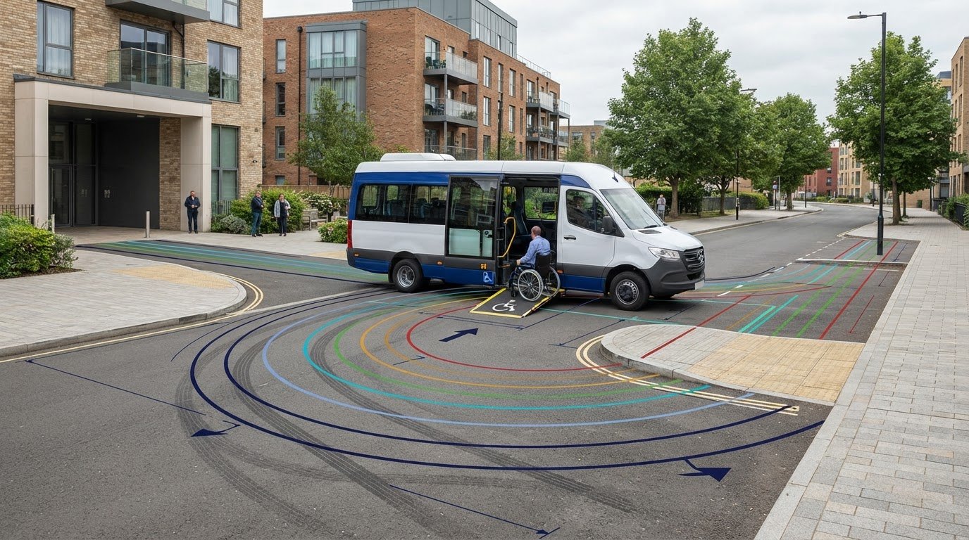
    Can a disabled access vehicle reach your site, manoeuvre where it needs to and leave again, while preserving space for passengers to board? Swept path analysis for disabled access vehicles tests whether a specific vehicle can make defined movements through a proposed layout. A turning path alone, however, won’t show whether there’s enough room to deploy a ramp or lift and support accessible boarding.

    A layout can look workable on plan but prove impractical in use. The result depends on testing the right vehicle dimensions and representative manoeuvres for the development, then interpreting the drawing in context. Vehicle movement and accessible boarding are related design considerations, but they are not the same assessment.

    This UK guide explains what a swept path drawing can demonstrate, what it can’t prove, and which vehicles and movements to consider. It also covers how to review project-specific evidence for design discussions and, where relevant, transport planning documentation and planning submissions.

    Key Takeaways

    • Swept path analysis for disabled access vehicles tests whether a chosen vehicle can follow defined routes through entrances, turning areas, drop-off points and exits.
    • Start with current site drawings, then select the vehicle and manoeuvres that reflect the project’s actual access conditions.
    • Use tracking results to assess vehicle movement alongside separate checks for boarding space, pedestrian routes and operational needs.
    • Before relying on a drawing, review its vehicle, route, dimensions, assumptions and clarity, and consider the relevant local planning and highway authority expectations.
    • Test access while the layout is still being developed to identify constraints early and inform design coordination or planning discussions.

    What does swept path analysis for disabled access vehicles demonstrate?

    Swept path analysis for disabled access vehicles is a drawing-based assessment of how a selected vehicle manoeuvres along a specified route. It can test whether the vehicle can enter a site, turn in a designated area, reach a drop-off point and leave without its tracked path conflicting with fixed features shown on the plan.

    The assessment focuses on vehicle movement. On its own, it doesn’t show whether passengers have enough space to board or alight, whether a ramp or lift can be deployed, or whether the pedestrian route is accessible. Those needs require separate design consideration. Overall suitability depends on the project’s intended use, the chosen vehicle, the site geometry and relevant planning or highway authority requirements.

    For an introduction to vehicle tracking tools, watch this overview of Autodesk Vehicle Tracking:

    Which vehicles might a project need to assess?

    The design vehicle should reflect how the site will actually be used. Depending on the development, this could be a wheelchair accessible vehicle (WAV), an accessible minibus or another vehicle expected to serve the building. Dimensions and manoeuvring characteristics vary, so a generic “disabled access vehicle” template won’t represent every scenario. Vehicle tracking software can assess different vehicle types; Swept Path Analysis Software provides background on how these tools are used to check vehicle movements.

    Consider the whole journey, not just the entrance. A vehicle may need to approach a drop-off area, turn or wait, then exit. Selecting a template that reflects the intended vehicle and its use makes the drawing more meaningful.

    What does the swept path drawing show?

    A drawing can show the vehicle body outline, wheel paths, direction of travel and sequence of manoeuvres. This helps the design team identify potential conflicts with boundaries, parked vehicles or street furniture. The drawing’s value depends on the information supplied, including an accurate site layout and clear vehicle assumptions.

    The drawing tests the stated route and conditions, not every possible real-world situation. Changes to the layout, vehicle or manoeuvre may affect the result. ML Traffic Engineers UK prepares project-specific swept path analysis to assess access feasibility and provide technical evidence for design discussions.

    How is a disabled access vehicle swept path assessment prepared?

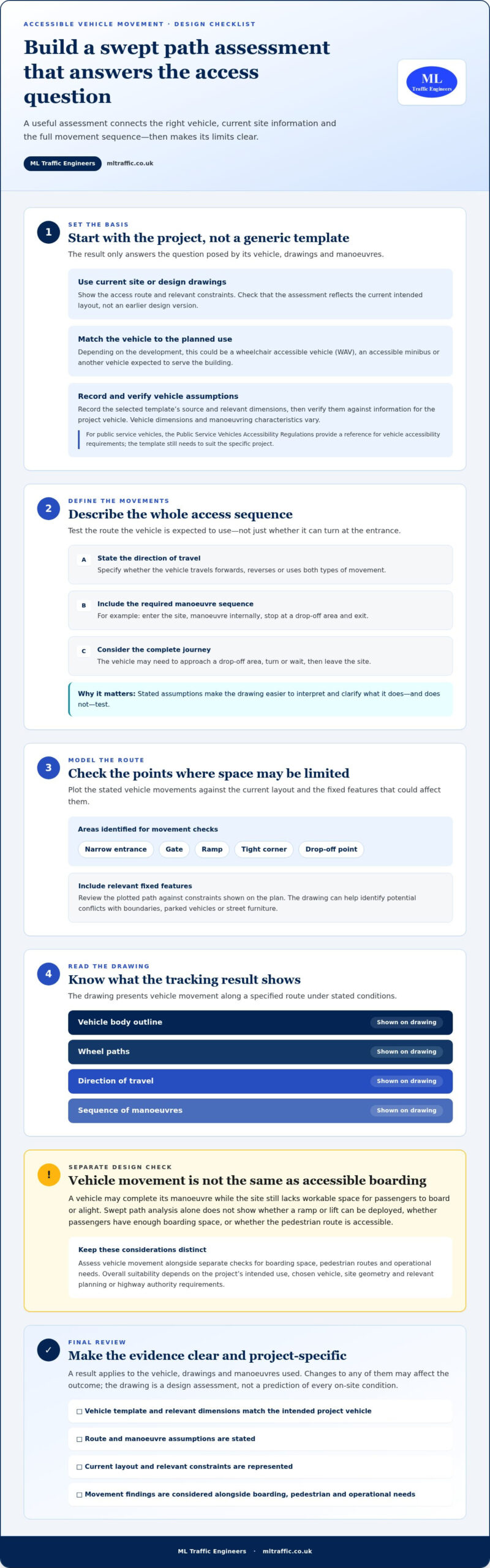
    A useful assessment follows a clear sequence: review the site information, select a representative vehicle, define the movements to test, model them against the layout, then review and present the results. Each step affects the next. If the drawings are outdated or the vehicle assumptions don’t match the intended use, the output may not answer the design question.

    Selecting the vehicle and movement assumptions

    Start with the facility’s planned use and the vehicles expected to serve it. A wheelchair accessible vehicle used for passenger drop-off may require a different assessment from an accessible minibus serving a community facility. Record the selected template’s source and relevant dimensions, then verify them against information for the project vehicle. For public service vehicles, the Public Service Vehicles Accessibility Regulations provide a reference for vehicle accessibility requirements. The assessment still needs a vehicle template suited to the specific project.

    Define whether the vehicle is expected to travel forwards, reverse or use both types of movement. Include the sequence required by the brief, such as entering, manoeuvring internally, stopping at a drop-off area and exiting. Stating these assumptions makes the drawing easier to interpret and clarifies what it does and doesn’t test.

    Modelling the complete access sequence

    Use current site or design drawings that show the access route and relevant constraints. Model movements where space may be limited, such as at a narrow entrance, gate, ramp, tight corner or drop-off point. Include fixed features that could affect vehicle movement, and make sure the test reflects the current intended layout rather than an earlier design version.

    The analyst reviews the plotted vehicle path against those features. If the vehicle cannot complete a required movement within the available space, the drawing can help pinpoint where the layout needs further consideration. This is a design assessment, not a prediction of every on-site condition. The result remains specific to the vehicle, drawings and manoeuvres used.

    For more context on software and drawing workflow, see this AutoTURN swept path analysis guide. A project-specific swept path analysis for disabled access vehicles can provide clear technical evidence for design coordination. Find out about swept path analysis for development projects.

    How should you compare vehicle tracking results with accessible site needs?

    A vehicle may complete its manoeuvre on the drawing while the site still lacks workable space for passengers to board, alight or continue along an accessible route. Read tracking results as one part of the design evidence, not as proof of inclusive access or a safe operating plan. Swept path analysis for disabled access vehicles tests the vehicle’s movement envelope under stated assumptions; it doesn’t assess every activity around the vehicle.

    Design consideration What to assess
    Vehicle movement Body outline, wheel paths, turning clearance and any encroachment during the tested manoeuvre.
    Boarding and alighting Space beside the stopping position for a passenger to use a ramp or lift and transfer between the vehicle and the site.
    Pedestrian route Whether people can move between the drop-off area, entrance and onward facilities without the vehicle path obstructing their route.
    Operations How the vehicle stops, whether it needs to reverse, and how parked vehicles or site features may affect the intended movement.

    Separate the swept path from the access journey

    Turning clearance shows whether the selected vehicle can follow the modelled route. Boarding space is a separate requirement. For example, a vehicle could reach a drop-off bay but leave insufficient room beside it for a ramp to be deployed. The pedestrian route beyond that bay also needs its own review. DfT guidance on disabled access for taxis addresses passenger access responsibilities in that context. Site design should also consider applicable inclusive design guidance, including BS 8300-1:2018 for the external environment and the DfT’s Inclusive Mobility guidance.

    Use constraints to inform design choices

    A plotted overlap, tight turn or need to reverse is a prompt for investigation, not automatically a compliance finding. Check what the drawing represents: the selected vehicle, assumed parked-car positions, fixed features and exact route can all affect the result. An omitted obstruction or a different vehicle may change the apparent clearance.

    Compare possible layout revisions using the same vehicle and movement assumptions. This helps show whether a change, such as adjusting a turning area or drop-off position, improves vehicle movement without compromising boarding space or the pedestrian route. Review the drawing alongside the wider design information before deciding whether the arrangement meets the project’s access needs.
    Swept Path Analysis for Disabled Access Vehicles: A UK Guide

    What should a UK design team check before relying on the analysis?

    Before using swept path analysis for disabled access vehicles in a design review or planning submission, check that the drawing answers the project’s specific access question. A clear result depends on a suitable vehicle, an accurate layout and stated movement assumptions. Treat the drawing as technical evidence for the manoeuvres shown, not as proof of full inclusive access compliance.

    A practical drawing review checklist

    Review the drawing and supporting information together. Confirm that it identifies:

    • Vehicle: the selected vehicle and the source of its template or dimensions.
    • Movement: the route, direction of travel and whether the manoeuvre uses forward movement, reversing or both.
    • Site plan: the latest design layout, including relevant boundaries and fixed obstructions such as gates, columns or street furniture.
    • Assumptions: any conditions that affect the test, such as the position of parked vehicles.
    • Clarity: legible paths and labels, with limitations explained rather than left in unexplained technical notation.

    If any of these details are unclear or out of date, the drawing may not represent the design being reviewed. Resolve discrepancies between the tracking plan and architectural or site drawings before relying on the result.

    Check national guidance and local expectations

    National guidance provides context, but the relevant planning and highway authority may set project-specific submission expectations. Check the current requirements for the site’s location, including the type of drawing or vehicle information requested. Guidance should only be cited where its scope applies: BS 8300-1:2018 addresses the external environment, while the Department for Transport’s Inclusive Mobility guide provides guidance on access to pedestrian and transport infrastructure. Confirm that the editions and recommendations remain current for the project.

    Coordination matters when the vehicle route, passenger drop-off, accessible entrance and pedestrian circulation appear across different drawings. Transport, access and architectural teams can align assumptions and identify gaps, such as a tracking plan that shows vehicle clearance but not the space needed for boarding or an unobstructed route. A swept path assessment can support wider transport planning documentation, but it doesn’t determine planning approval.

    ML Traffic Engineers provides project-specific swept path analysis based on the proposed layout and intended vehicle movements. Read about swept path analysis support.

    When should a project commission disabled access vehicle swept path analysis?

    Commission swept path analysis while the site layout is still being developed, before access geometry and building positions become difficult to change. Early testing can reveal whether the proposed vehicle route is workable and give the design team time to consider alternatives. A separate disabled access vehicle assessment is most useful when the vehicles expected to use the site or the complexity of their movements makes manoeuvrability a design question.

    Project situations that may benefit from early testing

    Early assessment can be useful where a proposed layout includes a constrained entrance, limited internal turning space, a designated drop-off point or a tight route to the exit. It can also help where a vehicle needs to pass a gate, negotiate a corner or manoeuvre within a compact site. Identifying a constraint while options are still open can inform layout discussions before the design is finalised.

    Consider testing when the access arrangement is being planned, and revisit the assessment if design changes affect the route, turning area or stopping position. A revised building layout or parking arrangement can alter the space available to manoeuvre. The assessment should reflect the current design and the vehicle movements relevant to the project, rather than rely on an earlier drawing.

    From swept path drawings to wider planning evidence

    Project-specific swept path analysis for disabled access vehicles can provide technical evidence for design coordination and planning discussions. Its findings may help the team understand whether a proposed access arrangement needs further consideration, and can inform associated transport documentation where relevant. A drawing remains evidence of the vehicle movements tested. It doesn’t establish full disabled access compliance or guarantee planning approval.

    ML Traffic Engineers prepares swept path analysis for development projects, focusing each assessment on the proposed layout, selected vehicle and required movements. Where a project also needs a Transport Statement or Transport Assessment, movement findings can contribute to the wider transport planning picture.

    For developments with a defined access route or constrained manoeuvring area, read about swept path analysis for vehicle access.

    Plan access with clear evidence

    Good access design starts with testing the movements a site is expected to accommodate. Swept path analysis for disabled access vehicles can show whether a selected vehicle can follow a defined route, but its value depends on accurate vehicle information, current drawings and clearly stated assumptions.

    Use the findings alongside separate consideration of boarding space, pedestrian routes and inclusive access. Also consider the relevant local planning and highway authority expectations. Together, these steps give the design team clearer evidence to discuss constraints and refine the layout before it is finalised.

    ML Traffic Engineers provides transport planning and traffic engineering services, including swept path analysis and planning documentation for development projects. The consultancy tailors the assessment to the site and proposed movements. The analysis can inform design discussions and support wider transport documentation where relevant, but it doesn’t guarantee planning approval or establish full accessibility compliance on its own.

    For a project-specific assessment, contact ML Traffic Engineers about your swept path analysis requirements. Clear evidence can help your team assess the proposed movements and coordinate the next design decisions.

    Frequently Asked Questions

    Is swept path analysis required for disabled access vehicles?

    There isn’t a universal requirement for swept path analysis for disabled access vehicles on every development. Whether it’s needed depends on the site, intended vehicle movements, access constraints and planning or highway authority expectations. A project-specific assessment can provide useful evidence where manoeuvrability is a design issue. For projects across Greater London, Manchester, Birmingham, the West Midlands, Liverpool, Surrey, East Sussex, West Sussex, Hampshire, Berkshire and Buckinghamshire, consider the relevant authority’s current requirements and applicable guidance.

    What vehicles should be included in a disabled access vehicle swept path analysis?

    Choose a vehicle that reflects the development’s intended use and access needs. Depending on the project, this might be a wheelchair accessible vehicle or an accessible minibus. Don’t assume one generic template represents every vehicle. Record the template source, relevant dimensions and movement assumptions, then compare them with the vehicle expected to serve the site. This keeps the assessment focused on a realistic design scenario.

    Does swept path analysis prove that a site is fully accessible?

    No. It demonstrates whether a specified vehicle can complete specified movements under the assumptions used in the assessment. On its own, it doesn’t assess accessible boarding and alighting space, the full pedestrian route, inclusive design or operational safety. Treat vehicle tracking as one part of a coordinated design review. Consider other access requirements separately, so successful manoeuvring isn’t mistaken for proof that every aspect of the site is accessible.

    Can a disabled access vehicle turn around on a restricted site?

    It depends on the vehicle’s dimensions, available site geometry, obstructions and the manoeuvre being tested. A swept path drawing can assess a defined turn and show potential conflicts with boundaries or fixed features. It can’t guarantee performance under every real-world condition. Test the vehicle and current layout together, including the intended approach and exit, to understand whether the proposed route accommodates the required movements.

    What information is needed for a disabled access vehicle swept path assessment?

    Provide current site or design drawings, details of the relevant vehicle or a verified template, the intended access movements and known obstructions. Clear information about the route and assumptions helps the design team interpret what the drawing demonstrates. Depending on the site’s complexity and assessment scope, further details may be needed. Outdated plans or unverified vehicle data can make the results less representative of the proposed design.

    When should swept path analysis be completed during design?

    Consider testing vehicle access while the layout can still be adjusted, then review the assessment against the latest design information. Early analysis may identify turning or access constraints before they become harder to resolve through design changes. Timing depends on the project programme and the evidence expected by the relevant planning or highway authority. Reassess if later changes affect the route, turning area or vehicle movements.

    Is swept path analysis the same as an accessible parking assessment?

    No. Swept path analysis tests how a vehicle moves along a defined route, while accessible parking and boarding involve other design considerations. Both may relate to the same site, but they answer different questions. A coordinated review should consider vehicle manoeuvring alongside parking arrangements, space for passengers to board or alight, and the pedestrian route to the destination. A turning result alone doesn’t establish that these other needs are met.

    Michael Lee

    Article by

    Michael Lee

    Transport planner with over 35 years' experience.

    Disclaimer

    The content on mltraffic.co.uk, including all technical articles, guides, and resources, is provided for general informational and educational purposes only. It is not intended to constitute professional advice in traffic engineering, transportation planning, development approvals, or any other technical or legal field.
    While ML Traffic Engineers makes every reasonable effort to ensure the accuracy, completeness, and timeliness of the information published, we do not provide any warranties or representations (express or implied) regarding its reliability, suitability, or availability for any particular purpose. Any reliance you place on the content is strictly at your own risk.
    In no event shall ML Traffic Engineers, its directors, employees, authors, or affiliates be liable for any direct, indirect, incidental, special, consequential, or punitive damages (including, without limitation, loss of profits, data, or business opportunities) arising out of or in connection with the use of, or inability to use, any information provided on this website.
    The articles and guides on this site are not a substitute for engaging a qualified, professional traffic engineer to assess your specific project requirements. For tailored advice, compliance assessments, or traffic engineering services, please contact a competent professional.
    This disclaimer may be updated from time to time without notice. By accessing or using this website, you agree to be bound by the most current version of this disclaimer.
  • What is a Vehicle Tracking Diagram?  A Guide for Developers

    What is a Vehicle Tracking Diagram? A Guide for Developers

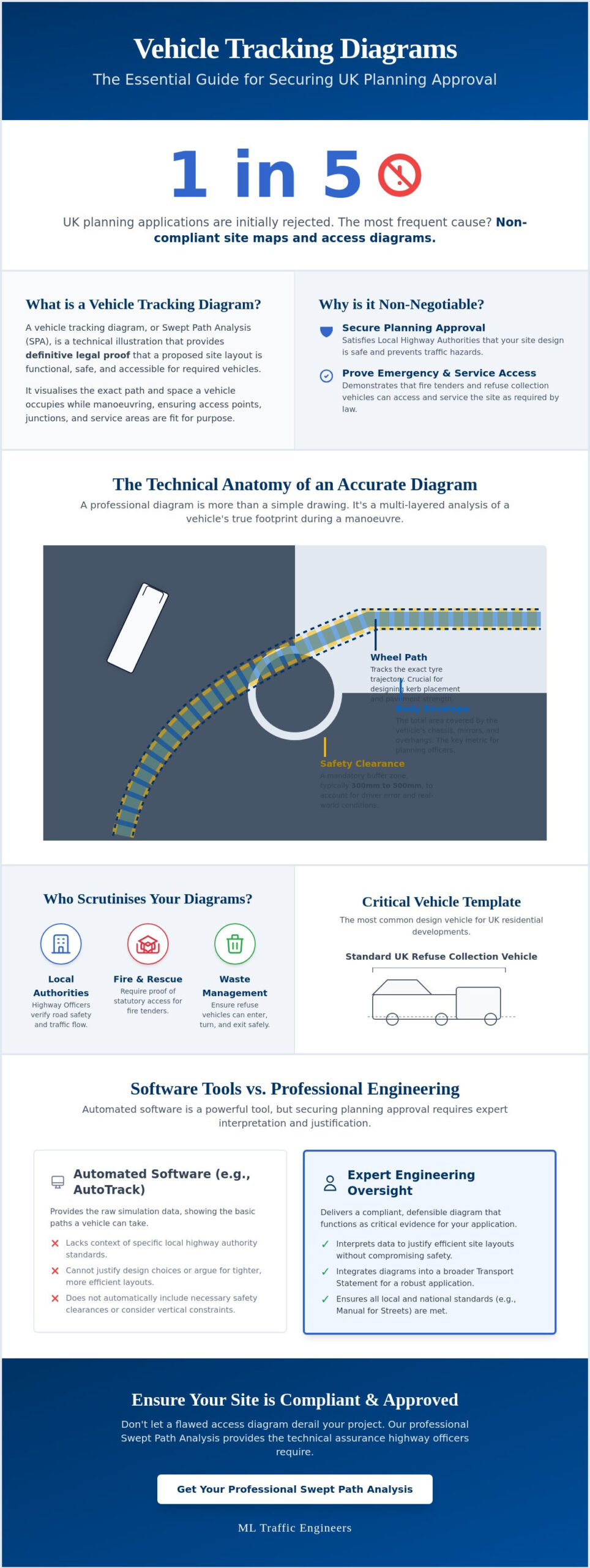
    Approximately one in five planning applications in the UK are initially rejected as invalid, with non-compliant site maps cited as the most frequent cause for failure. For any developer, a vehicle tracking diagram is far more than a simple technical drawing; it serves as the definitive legal proof that your proposed site layout is functional and safe. You likely recognize the stress of selecting the correct vehicle templates, such as fire tenders or refuse trucks, knowing that a single unworkable access point can lead to a costly planning refusal from the Local Highway Authority.

    We understand the pressure of meeting stringent highway standards while trying to maximize every square meter of your site. This guide provides a clear understanding of Swept Path Analysis (SPA) and explains how a professional vehicle tracking diagram functions as critical evidence for your application. You’ll learn how to ensure your layout meets the latest 2026 regulatory benchmarks, including updates to the Manual for Streets. We will preview how to bridge the gap between software features and engineering requirements to deliver a site that is both compliant and highly efficient.

    Key Takeaways

    • Understand why a vehicle tracking diagram is a mandatory requirement for proving site accessibility to Local Highway Authorities and emergency services.
    • Distinguish between wheel paths and body envelopes to ensure your layout accommodates the full physical footprint of a manoeuvring vehicle.
    • Identify the specific design templates required for your project, including the standard 11.4m refuse collection vehicle used by most UK councils.
    • Learn how professional interpretation of swept path data can justify tighter site layouts without compromising on safety or regulatory compliance.
    • Recognise the limitations of automated software and why expert engineering oversight is essential for securing planning approval.

    What is a Vehicle Tracking Diagram in UK Planning?

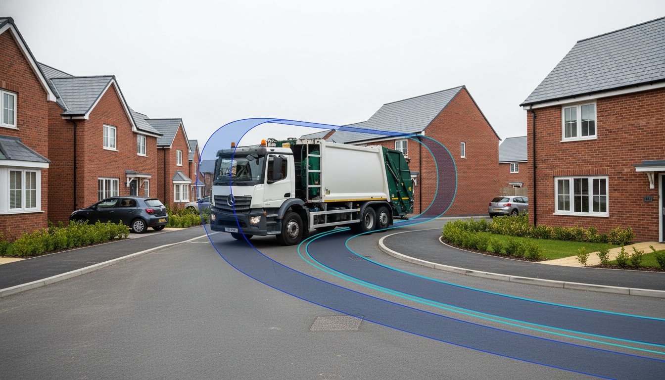
    A vehicle tracking diagram is a technical illustration that visualises the physical space required for a vehicle to manoeuvre through a site layout. It serves as a vital piece of evidence in the UK planning system, proving that a proposed design can safely accommodate the vehicles expected to use it. These diagrams aren’t just for show; they’re essential for securing approval from Local Highway Authorities who must ensure that emergency and service vehicles don’t get stuck or cause hazards on the public highway. By mapping the ‘swept path’ of a vehicle, developers can demonstrate that their site is functional before a single brick is laid.

    The role of these diagrams extends throughout the entire planning lifecycle. During the pre-application stage, they help identify potential access issues before they become expensive design flaws. Later, they’re frequently submitted as part of a formal application or used to discharge planning conditions once permission is granted. By integrating professional Swept Path Analysis services, developers provide the technical assurance that highway officers require to recommend an application for approval.

    A common oversight in many planning submissions is failing to integrate these diagrams into the broader Transport Statement. A vehicle tracking diagram shouldn’t stand alone. It provides the empirical data that supports the access and safety arguments within your Transport Statement. Without this visual proof, claims about site accessibility are merely anecdotal and often face immediate rejection from the council. Precision here is a functional necessity, not an optional extra.

    Terminology: Vehicle Tracking vs. Swept Path Analysis

    While often used interchangeably, ‘vehicle tracking’ refers to the simulation process itself, whereas the ‘diagram’ is the physical or digital output. This technical field has evolved significantly since the development of AutoTrack, the world’s first swept path analysis software. In professional engineering reports, ‘swept path’ specifically describes the area covered by the vehicle’s body plus a necessary safety margin. This margin is critical because it accounts for driver error and minor variations in vehicle dimensions, ensuring the layout works in the real world.

    Who Requires These Diagrams?

    Several statutory consultees will scrutinise your site’s accessibility. Local Planning Authorities (LPAs) and Highway Officers are the primary gatekeepers. They use these diagrams to verify road safety and traffic flow. Additionally, Fire and Rescue services require proof of statutory access for fire tenders to meet building regulations. Finally, waste management departments won’t approve a development unless a vehicle tracking diagram proves that a standard refuse collection vehicle can enter, turn, and exit the site safely in forward gear.

    The Technical Anatomy of an Accurate Tracking Diagram

    A professional vehicle tracking diagram is a composite of several critical data layers. It isn’t merely a drawing of a vehicle moving through a space; it’s a calculated projection of physical limits. The most fundamental layer is the ‘Wheel Path’, which tracks the exact trajectory of the tyres. This data is vital for engineers to determine curb heights and pavement structural requirements. However, the ‘Body Envelope’ is often the primary focus for planning officers. This represents the outer limits of the vehicle’s chassis, including mirrors and overhangs. In a tight turn, the body of a refuse truck or fire tender will often swing wider than the wheels. Ignoring this distinction is a common reason for planning failure.

    Precision is mandatory. Real-world driving isn’t perfect, so a safety clearance is essential. Most UK authorities expect a buffer of 300mm to 500mm between the vehicle’s body envelope and any physical obstruction like a wall or a parked car. For developments involving underground car parks or low bridges, vertical clearance must also be factored into the vehicle tracking diagram. A layout that works on a 2D plane might still fail if it doesn’t account for the height of a standard delivery van or emergency vehicle. If you’re concerned about these technical margins, our experts can provide a detailed Swept Path Analysis to ensure your site remains functional and compliant.

    Visual Standards for Planning Submission

    Clarity is just as important as accuracy. Planning officers often review dozens of applications a week, so your diagram must be legible and professional. High-resolution PDF outputs are the industry standard; raw CAD files are rarely accepted because they require specialised software to view. We recommend colour-coding different vehicle types to make the diagram intuitive. For example, using red for fire tenders and blue for passenger cars allows a reviewer to quickly verify access for different services. Adhering to these UK government requirements for vehicle tracking plans ensures your base map, typically an OS MasterMap, is up-to-date and provides an accurate context for the manoeuvres.

    Interpreting ‘Lock-to-Lock’ Time

    One technical detail that frequently trips up developers is ‘lock-to-lock’ time. This is the time it takes a driver to turn the steering wheel from one extreme to the other. If a diagram assumes a steering speed that’s too fast for a heavy refuse vehicle, the resulting arc will be unrealistically tight. Most residential manoeuvres occur at slow speeds, often under 5mph. Your vehicle tracking diagram must reflect these slow-speed realities. Applications are often rejected when highway officers spot steering assumptions that don’t align with the physical capabilities of the chosen design vehicle.

    Software Tools vs. Professional Engineering Services

    Autodesk Vehicle Tracking has become the dominant force in digital site modeling, providing developers with powerful tools to simulate vehicle movement. While this software is the industry standard for precision, it’s vital to remember that it is a tool, not a solution. A vehicle tracking diagram generated by a computer is only as reliable as the parameters defined by the operator. Simply owning the software doesn’t mean a developer can produce a document that will withstand the scrutiny of a Local Highway Authority. Expert interpretation remains the bridge between a technical drawing and a successful planning approval.

    One of the most significant risks in using automated software is the reliance on ‘default settings’. Standard vehicle libraries often include templates that don’t align with specific UK council requirements. For instance, using a generic ‘Garbage Truck’ template might result in a manoeuvre that is either too optimistic or unnecessarily restrictive. Most English councils require a specific 11.4m Refuse Collection Vehicle (RCV) template. If your diagram uses a 10.5m default model, your application will likely be rejected for being ‘unworkable’. Hiring a transport consultant ensures that the correct, council-specific design vehicles are used from the start, avoiding costly redesigns.

    The Limitations of Automated Software

    Software lacks the ability to understand local policy or the nuances of the ‘human element’ in driving. While a computer might flag a turn as ‘failing’ because of a 50mm overlap, an experienced engineer can often optimise the layout or provide a technical justification for the manoeuvre. We focus on finding functional solutions that maximise your site’s developable area. A professional report includes the commentary necessary to explain why a specific path is safe, even in ‘tight’ site layouts that automated software might struggle to validate.

    Why Professional Certification Matters

    Highway Officers give significantly more weight to a vehicle tracking diagram submitted by a recognised traffic engineering firm. This isn’t just about the drawing; it’s about the accountability that comes with it. Professional firms carry Professional Indemnity (PI) insurance, which protects the developer against design errors that could lead to structural or operational failures. Furthermore, we ensure these diagrams are seamlessly integrated into a comprehensive Transport Statement London. This holistic approach provides the statutory consultees with all the evidence they need in a single, authoritative package, significantly reducing the likelihood of a planning refusal.

    What is a Vehicle Tracking Diagram? A Guide for Developers

    Critical Vehicle Templates for UK Planning Approval

    Selecting the correct ‘Design Vehicle’ is the most consequential decision in the creation of a vehicle tracking diagram. A design vehicle is the largest or most frequent vehicle expected to use the site, and its dimensions dictate the layout’s feasibility. Using a generic or undersized template is a common error that leads to immediate planning rejection. For most residential developments in England, the 11.4m Refuse Collection Vehicle (RCV) is the non-negotiable standard. Highway officers require proof that this specific vehicle can navigate the site without mounting kerbs or endangering pedestrians.

    Statutory access for emergency services is equally critical. Fire tenders must meet the 12.5m outer turning circle rule, as specified in Building Regulations. If your site layout cannot accommodate this manoeuvre, it won’t pass safety inspections regardless of how well the rest of the design performs. For commercial and retail schemes, the focus shifts to delivery logistics. This often requires tracking for 16.5m Articulated HGVs or smaller Rigid HGVs for urban environments. If you are unsure which templates your local council requires, our team can provide expert Swept Path Analysis to ensure your submission is accurate from the start.

    Residential Development Requirements

    In residential schemes, the vehicle tracking diagram must demonstrate that refuse trucks can enter and exit in forward gear. This often involves designing ‘turning heads’ at the end of cul-de-sacs. If a dead-end road is longer than 20 metres, a turning facility is a mandatory requirement for fire access. Larger residential developments may also need to show tracking for a Pantechnicon, or standard removal van, to ensure residents can move in and out without blocking the entire street. For premium developments, ensuring that high-end private hire services like Hyper Executive Travel can easily access drop-off points is equally important for the end-user experience. Precision here prevents the ‘unworkable’ label that highway officers often apply to poorly planned access points.

    Commercial and Industrial Standards

    Industrial developments face different challenges, particularly regarding warehouse loading bays. These sites require tracking for 16.5m Articulated HGVs to prove that vehicles can reverse into bays without multiple shunts that disrupt traffic flow. Urban retail units often rely on Rigid HGV templates, which are more manoeuvrable but still require significant clearance. Some specialist developments, such as petrol stations or industrial plants, may even require tracking for fuel tankers or abnormal loads. For developers managing the logistics of industrial site setup, silver-knight.co.uk offers a detailed guide on heavy equipment transport costs. We ensure every vehicle tracking diagram uses the specific manufacturer data required for these high-stakes manoeuvres, maintaining the safety-conscious standards your project demands.

    Securing Planning Approval with Accurate Vehicle Tracking

    A professional vehicle tracking diagram serves as a persuasive tool during negotiations with the Local Highway Authority. It transforms subjective concerns about site access into objective, data-driven discussions. When a highway officer or a local resident raises an objection based on perceived congestion or “unworkable” turns, your diagram provides the empirical proof needed to mitigate those concerns. By demonstrating that every manoeuvre is within safe physical limits, you can often justify “tight” site layouts that maximise your developable land without compromising on safety standards.

    Engaging in pre-application tracking is one of the most effective ways to avoid expensive redesigns. Identifying a conflict between a refuse truck’s body envelope and a proposed building corner is far easier to fix during the initial design phase than after a formal submission. At ML Traffic Engineers UK, we provide compliant, planning-ready documentation that integrates seamlessly into your wider application. We ensure that every vehicle tracking diagram we produce adheres to the latest 2026 standards, providing the technical authority required to satisfy statutory consultees and streamline the approval process.

    Integrating Tracking into Your Design Process

    Tracking should never be an afterthought. We recommend conducting a Swept Path Analysis before your final site plan is frozen. This proactive approach allows you to determine the absolute minimum road widths required for safe passage. It also helps you find the critical balance between maximizing parking provision and ensuring necessary vehicle manoeuvrability. When you design with tracking data from the start, you create a layout that is both functional for users and acceptable to highway officers.

    Next Steps for Your Planning Application

    Securing a professional assessment is a straightforward process that provides immediate clarity for your project. You can request a quote for a professional Swept Path Analysis by contacting our team with your current site plans. We understand the urgency of planning deadlines; we prioritise efficient turnaround times to keep your application moving forward. For more developer guides and technical insights, visit our resources page. Our goal is to act as your dependable partner, managing the intricate regional regulations so you can focus on the broader vision of your development.

    Advancing Your Development with Technical Certainty

    A compliant site layout depends on more than just a drawing; it requires the precise application of highway standards and physical limits. You’ve seen how the body envelope and safety clearances dictate the success of your application. Choosing the correct design vehicles, from refuse trucks to fire tenders, ensures your layout remains functional under real-world conditions. A professional vehicle tracking diagram acts as your definitive evidence against planning objections and helps you avoid the high costs of post-submission redesigns.

    Expertise matters when navigating the specific requirements of London and England planning authorities. We provide technical analysis that is accepted by all UK Highway Authorities, ensuring your project meets every regulatory benchmark. We understand that planning deadlines move quickly, so we offer a rapid turnaround to keep your development on track. Request a Professional Swept Path Analysis for Your Project today to secure your site access. Our team is ready to provide the precision your application needs for a smooth path to approval.

    Frequently Asked Questions

    Is a vehicle tracking diagram required for every planning application?

    Not all applications require a vehicle tracking diagram, but they’re mandatory for any development creating new access points or involving significant changes to vehicle movement. Local Highway Authorities typically demand them for residential schemes of three or more dwellings and all commercial developments. If your project requires service or emergency vehicle access, you’ll need to provide this technical proof to avoid an invalid application status.

    What is the standard size of a fire tender for UK swept path analysis?

    The standard fire tender used for UK swept path analysis typically measures 8 metres in length and 2.55 metres in width. However, the most critical metric is the 12.5 metre outer turning circle requirement specified in Building Regulations. We ensure your diagram accounts for these dimensions plus the necessary safety buffers to ensure statutory access is guaranteed for emergency services without any risk of collision.

    Can I use a standard car for my tracking diagram?

    You can use a standard car template for tracking individual parking spaces, but it won’t satisfy access requirements for a planning application. Highway officers focus on the largest vehicles expected on site, such as refuse trucks or fire tenders. A vehicle tracking diagram that only shows a passenger car doesn’t prove that the site is functional for essential services or emergency responders.

    What happens if my site layout fails the vehicle tracking test?

    If your site layout fails the test, you’ll need to redesign the access or turning areas before submitting your application. This often involves widening internal junctions, increasing the radius of a turning head, or slightly relocating buildings to provide the necessary clearance. Identifying these failures during the pre-application stage prevents a formal refusal and the associated costs of starting the process over again.

    Do I need a separate diagram for every entrance and exit?

    You must provide tracking for every entrance and exit that serves different vehicle types or has unique geometric constraints. While you don’t necessarily need separate drawings, the diagrams must clearly show that all access points are functional for their intended use. This includes demonstrating that a refuse truck can safely enter and exit the site in forward gear at every designated point.

    How much does a professional swept path analysis cost in 2026?

    The cost of a professional swept path analysis varies depending on the complexity of the site and the number of vehicle manoeuvres required. While industry rates in London for standard CAD assessments can range significantly, every project has unique requirements. We recommend requesting a tailored quote to ensure you receive a comprehensive report that meets your specific local authority’s stringent standards.

    What software do transport engineers use for vehicle tracking?

    Transport engineers primarily use specialised software such as Autodesk Vehicle Tracking, AutoTURN 2026, and RapidPath. These tools allow us to simulate precise manoeuvres using up-to-date libraries of UK-specific vehicle templates. By using industry-standard software, we produce a verifiable vehicle tracking diagram that highway officers can trust, ensuring your technical evidence aligns with the digital systems used by local planning departments.

    Does the diagram need to show the vehicle reversing?

    Your diagram must show reversing manoeuvres if they’re a necessary part of the site’s operation, such as in turning heads or loading bays. However, councils generally prefer designs that allow refuse and emergency vehicles to enter and exit in forward gear. If reversing is required, the diagram must prove the manoeuvre is safe and doesn’t conflict with pedestrian paths or structural boundaries.

    Michael Lee

    Article by

    Michael Lee

    Transport planner with over 35 years' experience.

    Disclaimer

    The content on mltraffic.co.uk, including all technical articles, guides, and resources, is provided for general informational and educational purposes only. It is not intended to constitute professional advice in traffic engineering, transportation planning, development approvals, or any other technical or legal field.
    While ML Traffic Engineers makes every reasonable effort to ensure the accuracy, completeness, and timeliness of the information published, we do not provide any warranties or representations (express or implied) regarding its reliability, suitability, or availability for any particular purpose. Any reliance you place on the content is strictly at your own risk.
    In no event shall ML Traffic Engineers, its directors, employees, authors, or affiliates be liable for any direct, indirect, incidental, special, consequential, or punitive damages (including, without limitation, loss of profits, data, or business opportunities) arising out of or in connection with the use of, or inability to use, any information provided on this website.
    The articles and guides on this site are not a substitute for engaging a qualified, professional traffic engineer to assess your specific project requirements. For tailored advice, compliance assessments, or traffic engineering services, please contact a competent professional.
    This disclaimer may be updated from time to time without notice. By accessing or using this website, you agree to be bound by the most current version of this disclaimer.