Tag: Access Design

  • How to create an 11.4m refuse vehicle swept path diagram without CAD

    How to create an 11.4m refuse vehicle swept path diagram without CAD

    A swept path analysis for an 11.4m local authority refuse collection vehicle can be prepared without CAD by using a scaled plan, the authority-specified vehicle data and a clear record of each manoeuvre. In Bristol, design vehicles will normally include an 11.4 m refuse vehicle and emergency vehicles, so the correct vehicle selection is the starting point.

    You don’t need specialist drawing software to make a diagram easy to follow, but you do need a consistent scale and enough detail to show where the vehicle travels. If the drawing omits the swept envelope or makes clearances difficult to judge, reviewers may not have the evidence they need.

    This guide explains how to identify the required design vehicle, prepare a scaled base plan and trace the manoeuvre by hand. It also covers how to label the swept envelope, record clearances and present the drawing so its assumptions and limitations are clear. The goal is a practical, transparent diagram that helps assess access before the layout is finalised.

    Key Takeaways

    • Use the authority’s vehicle requirements to guide your selection, rather than relying on a generic refuse vehicle template.
    • Build the manoeuvre around a scaled base plan, tracing the vehicle’s movement through the full access route.
    • Make the swept envelope and the relationship to nearby boundaries and obstacles clear on the drawing.
    • Label the plan so reviewers can understand its scale, vehicle assumptions and intended route without guessing.
    • Learn when a professionally prepared Swept Path Analysis can help resolve access and layout questions.

    Choosing the authority-specified design vehicle

    Local authorities set access expectations through their transport or waste-collection guidance and development review. Requirements can address vehicle dimensions, gradients, headroom and turning facilities; use the criteria that apply to the site rather than assuming one standard covers every authority.

    1. Identify the authority responsible for the site. Find the council’s transport, highways or waste-collection guidance, then locate its access and vehicle requirements. Check the documents relevant to the proposed development and note any project-specific instructions. This establishes the design basis before drawing begins and helps avoid relying on an unrelated council’s criteria.
    2. Record the specified vehicle and its source. Write down the vehicle description exactly as the authority gives it, including any stated length or configuration. For an assessment using an 11.4 m refuse vehicle, record that length alongside the relevant vehicle description. Retain the source document or design instruction in the drawing notes so the selected vehicle can be traced to the project requirements.
    3. Use matching vehicle geometry. Obtain dimensions and turning data for the specified vehicle rather than estimating its movement from overall length. Body width, wheelbase, overhangs and steering behaviour affect the space occupied during a manoeuvre. Keep the data source and assumptions with the working drawing. Don’t substitute a smaller or differently configured vehicle simply because its template is easier to obtain.
    4. Translate access criteria into drawing checks. List the requirements the authority expects the layout to demonstrate, such as route width, gradient changes, overhead clearance and turning space. Link each criterion to the relevant part of the plan or supporting detail. For example, identify where a structure could affect headroom instead of describing the entire route as clear without showing the constraint.
    5. Resolve differences before tracing the route. Compare the authority’s vehicle description with the available vehicle data. If the stated design vehicle and the available template describe different configurations, retain the authority’s design basis and use matching geometry. Assess gradients and headroom against the site’s levels and constraints; a plan without relevant level information cannot demonstrate those conditions.
    6. Set out the assumptions transparently. Add the responsible authority, guidance document, vehicle description and data source to the working notes. State which movements the drawing tests, including entry, turning and exit where required. Clear notes make the design basis traceable and help prevent a precise-looking diagram from being mistaken for evidence about another vehicle.

    Which vehicle goes on the diagram?

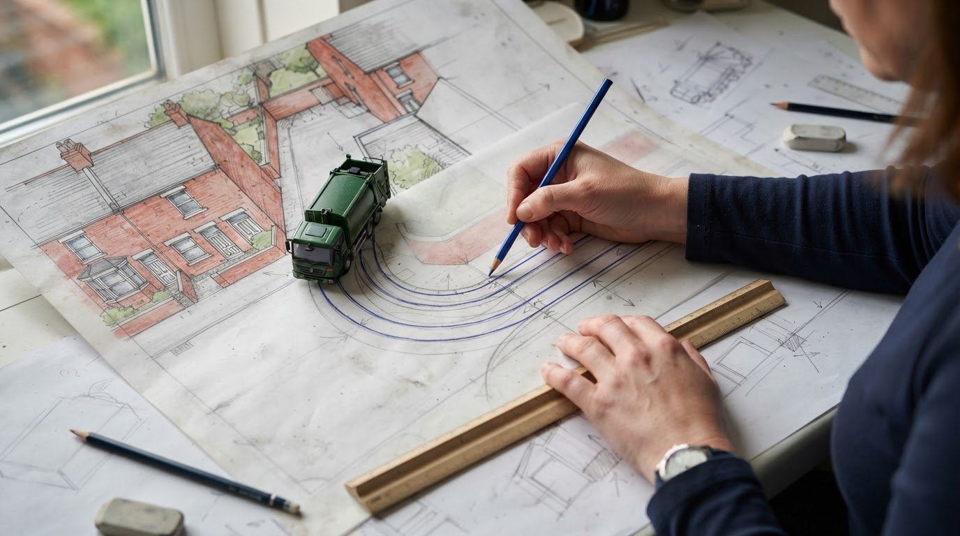
    Choose the vehicle that matches the authority’s requirement, then use its geometry to test the route. A swept path analysis for an 11.4m local authority refuse collection vehicle must represent that specified vehicle, not a smaller substitute.

    1. Compare refuse vehicle access needs

      Compare the authority-specified 11.4 m vehicle with any smaller refuse vehicle proposed for the site. The larger design vehicle can require more space to turn and manoeuvre, so a route that accommodates a smaller vehicle may not suit the specified one. Don’t use a smaller vehicle’s diagram as evidence for access by the required vehicle.

      Birmingham City Council’s Highways Developers Guide refers to DB32 Appendix 1 diagrams for turning heads designed using swept path analysis. Treat this as a reference for turning-head diagrams, not a replacement for the local authority’s specified vehicle. Keep the chosen vehicle and movement being tested clear in the drawing notes.

    2. Record vehicle dimensions and turning characteristics

      Record the selected template’s overall length, width, wheelbase, front and rear overhangs, and steering characteristics. The 11.4 m length alone cannot establish the turning path or the vehicle’s full footprint. These details depend on the vehicle configuration, so use geometry that matches the specified refuse vehicle rather than a general heavy-vehicle outline.

      Check that the template shows both the vehicle body and wheel paths. During a turn, rear wheels can track inside the front wheels, while the body’s corners occupy additional space. A swept path analysis for an 11.4m local authority refuse collection vehicle should therefore use complete vehicle geometry when testing a tight entrance, turning head or constrained junction.

    3. Select software and vehicle templates

      Choose a swept-path package and template that match the authority’s design vehicle. AutoTURN is one option for plotting vehicle movement paths, but its template must still represent the required vehicle’s dimensions and steering behaviour. Don’t assume a generic heavy-vehicle template is equivalent without comparing its geometry.

      A non-CAD workflow can plot successive vehicle positions on a scaled plan using reliable vehicle data. Keep the source dimensions with the drawing and distinguish the body outline from the wheel paths. The method may vary, but the selected vehicle and its geometry must remain consistent.

    4. Assemble the information for the analysis

      Provide the site plan, access layout, relevant constraints and the authority’s vehicle requirement. Include the vehicle’s dimensions and turning data, the movements to test, and any site levels or overhead obstructions that affect the route. This establishes a clear site and vehicle basis, rather than presenting an illustrative turn without stated assumptions.

      For a swept path analysis for an 11.4m local authority refuse collection vehicle, keep the movement requirements aligned with the proposed access. This helps the resulting diagram test the route the development will actually rely on.

    Documenting and exporting swept-path drawings

    1. Set a suitable drawing scale. Choose a scale that keeps the route and vehicle envelope legible on the sheet, and follow the receiving UK authority’s drawing requirements. No single scale applies universally to every UK submission. Show the chosen scale on the drawing and use it consistently from the base plan to the exported file.

      Add a scale bar as well as a scale note. If someone views or prints the PDF at a different size, the bar helps them interpret distances without relying only on page dimensions.

    2. Prepare a clear base plan. Show the access route, kerbs, boundaries, buildings and fixed obstacles that affect vehicle movement. Use distinct line weights for site features, vehicle outlines and swept paths. If a gate or narrow access point controls the turn, mark it clearly so reviewers don’t have to infer its position.

      Show enough of the approach and exit to explain how the vehicle reaches and leaves the manoeuvre. A drawing cropped tightly around a turning head may hide constraints on the adjoining route.

    3. Make the movement easy to follow. Distinguish the swept envelope, wheel paths and vehicle body using clear line styles or colours. Add direction arrows for entry, forward travel, reversing and exit. If the vehicle changes direction within a turning area, show the sequence so every part of the manoeuvre is clear.

      Where paths overlap, use a small key or distinct line patterns to separate them. Place the key outside the access route so it does not obscure the area being assessed.

    4. Document the design basis on the sheet. Include the vehicle description, source of its dimensions, drawing scale and movements tested. Identify the local authority’s specified design vehicle where applicable. These notes link the diagram to its assumptions and help prevent it being mistaken for evidence relating to another vehicle.

      Keep limitations specific to the drawing. For example, state if it shows the entry movement but not the vehicle’s exit route.

    5. Inspect the exported file before issue. Export the drawing as a PDF and review it at the intended page size. Confirm that labels are readable, line styles remain distinct, and the scale bar and notes are visible. Compare the PDF with the working drawing to catch clipped text, missing layers or a shifted base plan.

      Use a descriptive file name that identifies the site, vehicle and revision. Keep the issued PDF separate from working drafts so the submitted drawing is easy to identify.
    How to create an 11.4m refuse vehicle swept path diagram without CAD

    Drawing vehicle manoeuvres

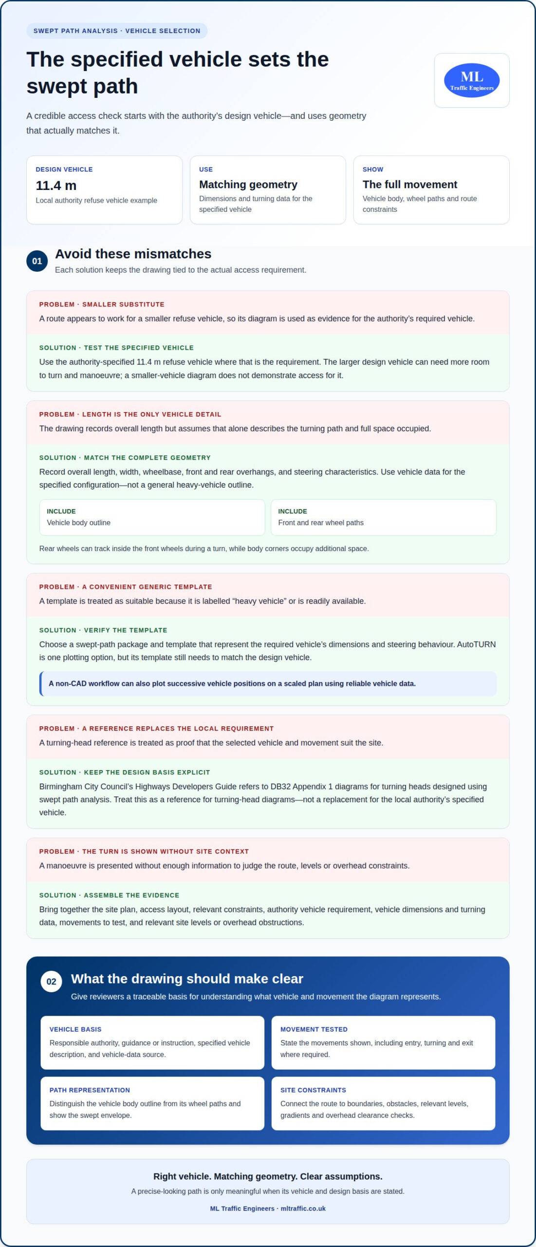
    Work from the scaled site plan and the selected vehicle geometry. Draw each movement in sequence to show how the refuse vehicle enters, turns and leaves.

    1. Mark the route and control points. Identify the entrance, kerb lines, turning area and exit on the base plan. Mark any gate, parked-vehicle area, wall or other fixed feature that could affect movement. These control points show where the vehicle must pass and where the manoeuvre needs closer attention.

      For example, a narrow entrance followed by a turn means both the approach and the turn must appear on the drawing. Don’t crop the plan to show only the turning head.

    2. Set the vehicle’s starting position. Place the vehicle on the approach, aligned with the route. Use the front, rear and wheel positions from the selected geometry, not a rough rectangle. The starting position should show how the vehicle reaches the site entrance before steering begins.

      Keep the vehicle outline parallel to the approach where the road allows. If the approach curves, show that alignment instead of forcing a straight entry.

    3. Trace the steering movement in stages. Draw successive vehicle positions through the turn, changing the heading gradually. At each position, retain the full body outline and wheel locations. This shows how the front corners swing outward while the rear wheels follow a different track.

      Use enough intermediate positions to make the path clear. An outline only at the start and finish can hide the space occupied between them.

    4. Include every direction change. Where the route requires forward and reverse movements, show them as separate parts of the manoeuvre. Add direction arrows and distinguish each movement with a clear line style. For a multi-point turn, make the order of forward and reversing movements visible.

      Don’t merge overlapping paths into an indistinct mark. Reviewers need to understand which vehicle position belongs to each part of the turn.

    5. Repeat the tracing for the complete route. Continue from the turn to the site exit, including any change in alignment at a junction or access throat. Check that the final position leads into the intended exit route. A diagram showing entry but not exit leaves the full vehicle movement untested.

      If the vehicle passes close to a boundary, keep that feature visible in the drawing. The relationship between the vehicle outline and the site layout is part of the assessment.

    6. Review the drawing as a sequence. Follow the arrows from approach to departure and confirm that each outline connects logically to the next. Look for gaps in the route, unclear overlaps or a vehicle position that appears to jump across the plan.

      Then compare the plotted path with the underlying plan. Misaligned tracing can make a workable route appear clear or conceal a conflict with a kerb, wall or other fixed feature.

    Reading swept envelopes and clearances

    Compare the envelope with site features to identify where the vehicle comes closest to an obstruction. Assess every part of the route, not just the turning point.

    1. Check road widths and turning radii

      Compare the swept envelope with the available carriageway and turning area; no single minimum width or turning radius applies to every 11.4 m refuse vehicle and site layout. The required space depends on the selected vehicle’s geometry, steering path, approach angle and nearby boundaries, so assess the authority-specified vehicle on the actual plan.

      At a bend, check both the inner rear-wheel path and the outer body swing. Road width alone cannot show whether a vehicle can negotiate a junction or turning head.

    2. Identify design failures and safety risks

      Trace the full vehicle outline beside kerbs, walls, gates and parked-car areas. Common design failures include a rear wheel crossing a kerb, a front corner clipping a boundary, or the body overhanging a pedestrian route. A turning diagram can also reveal a route that relies on reversing when the layout assumes forward movement.

      Review each conflict in context. An envelope crossing a fixed obstruction indicates a geometric conflict; overlap with a pedestrian area highlights a potential interface that needs design attention.

    3. Read the full envelope, not only the wheel tracks. Wheel paths show where the tyres travel, while the body outline captures front and rear overhang. Compare both with the plan. For example, the rear wheels may clear a kerb while a front corner swings towards a wall.

      Check every plotted vehicle position throughout the manoeuvre. A clear starting and finishing position does not prove the space between them is clear.

    4. Assess clearances at the tightest points. Locate the narrowest gap between the envelope and a fixed feature, such as a gatepost or building corner. Make sure the scale and linework let readers distinguish a genuine gap from contact or overlap. Keep the relevant feature visible on the plan.

      If the plan includes a height constraint, assess overhead clearance separately from the horizontal envelope. A plan view alone cannot demonstrate clearance beneath a canopy or overhang.

    5. Record conflicts and refine the layout. Mark each pinch point and identify the vehicle movement that creates it. Then test a layout change, such as adjusting a kerb line or turning area, against the same vehicle path. Keep the revised drawing and its assumptions clear so the comparison shows what changed.

      For a project-specific review of vehicle paths and site clearances, request a swept path analysis based on the proposed layout and design vehicle.

    ML Traffic Engineers UK: Swept Path Analysis

    ML Traffic Engineers UK provides Swept Path Analysis to assess whether a proposed site layout accommodates the authority-specified refuse vehicle. Use the service when an access route, turning head or constrained entrance needs a clear, documented assessment of vehicle movements.

    The analysis shows the vehicle path against the site layout, helping identify potential conflicts with boundaries, kerbs and other fixed features. Provide the site plan and vehicle requirement so the assessment addresses the intended access movements. If the planning submission also needs transport documentation, a Transport Statement or Transport Assessment may support the project.

    Contact ML Traffic Engineers UK to discuss Swept Path Analysis for your proposed layout.

    Move your access design forward

    A clear swept path analysis for an 11.4m local authority refuse collection vehicle can help you address vehicle access while the site layout is still being developed. The next step is to relate the movement assessment to the planning information your project needs, so access constraints can inform design decisions and supporting documentation.

    ML Traffic Engineers UK provides Swept Path Analysis, alongside Transport Statements and Parking Surveys where they fit the project’s requirements. Each addresses a different transport-planning need, helping provide relevant evidence for a development proposal.

    Share your proposed layout and authority vehicle requirement with ML Traffic Engineers UK to discuss the appropriate next step. Contact ML Traffic Engineers UK to move your access assessment forward with a clear design basis.

    Frequently Asked Questions

    What UK design vehicle standards apply to refuse collection vehicles in swept path analysis?

    Use the design vehicle specified for the site by its relevant local authority. Requirements can differ between authorities, so a vehicle template used elsewhere may not match the local design basis. For example, Bristol’s design vehicles will normally include an 11.4 m refuse vehicle and emergency vehicles. Record the vehicle description and dimensions used, then ensure the drawn movement represents that vehicle rather than a generic refuse lorry.

    How should swept path analysis account for vehicle body overhang, tracking width and clearance margins?

    Assess the body outline and wheel paths separately because they show different aspects of vehicle movement. At a bend, the rear wheels may track inside the front-wheel path while the front or rear body corners swing towards nearby features. For example, a wheel path may clear a kerb while a body corner approaches a wall. Show the tightest clearances against fixed site features and keep the vehicle geometry consistent throughout the manoeuvre.

    What UK highway guidance covers refuse vehicle access and turning areas in new developments?

    Check the guidance used by the highway authority reviewing the development. Bristol City Council’s Transport Development Management Guidance on turning and swept paths is dated October 2022. Birmingham City Council’s Highways Developers Guide refers to DB32 Appendix 1 diagrams for turning heads designed using swept path analysis. Treat these as authority-specific references, then use the applicable local requirements for the site rather than assuming one document governs every UK development.

    Which local authority planning or waste collection standards should be checked for a specific UK site?

    Start with the planning or transport guidance for the council responsible for the site, then review its waste collection requirements and any project-specific design brief. A scheme in Birmingham, for example, should account for the turning-head reference in Birmingham City Council’s Highways Developers Guide; a Bristol scheme has its own turning and swept-path guidance. For sites in Greater London, Manchester, Birmingham, Liverpool, Surrey, East Sussex, West Sussex, Hampshire, Berkshire, Buckinghamshire or the West Midlands, identify the relevant authority’s documents before setting the vehicle design basis.

    What vehicle dimensions and turning characteristics are typical for an 11.4 m local authority refuse collection vehicle?

    The vehicle is 11.4 m long. Its width, wheelbase, front and rear overhangs, and steering characteristics depend on its configuration, so use matching vehicle data rather than assuming standard values.

    Michael Lee

    Article by

    Michael Lee

    Transport planner with over 35 years' experience.

    Disclaimer

    The content on mltraffic.co.uk, including all technical articles, guides, and resources, is provided for general informational and educational purposes only. It is not intended to constitute professional advice in traffic engineering, transportation planning, development approvals, or any other technical or legal field.
    While ML Traffic Engineers makes every reasonable effort to ensure the accuracy, completeness, and timeliness of the information published, we do not provide any warranties or representations (express or implied) regarding its reliability, suitability, or availability for any particular purpose. Any reliance you place on the content is strictly at your own risk.
    In no event shall ML Traffic Engineers, its directors, employees, authors, or affiliates be liable for any direct, indirect, incidental, special, consequential, or punitive damages (including, without limitation, loss of profits, data, or business opportunities) arising out of or in connection with the use of, or inability to use, any information provided on this website.
    The articles and guides on this site are not a substitute for engaging a qualified, professional traffic engineer to assess your specific project requirements. For tailored advice, compliance assessments, or traffic engineering services, please contact a competent professional.
    This disclaimer may be updated from time to time without notice. By accessing or using this website, you agree to be bound by the most current version of this disclaimer.
  • Swept Path Analysis for Fire Appliance Access

    Swept Path Analysis for Fire Appliance Access

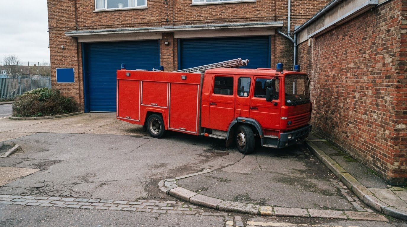
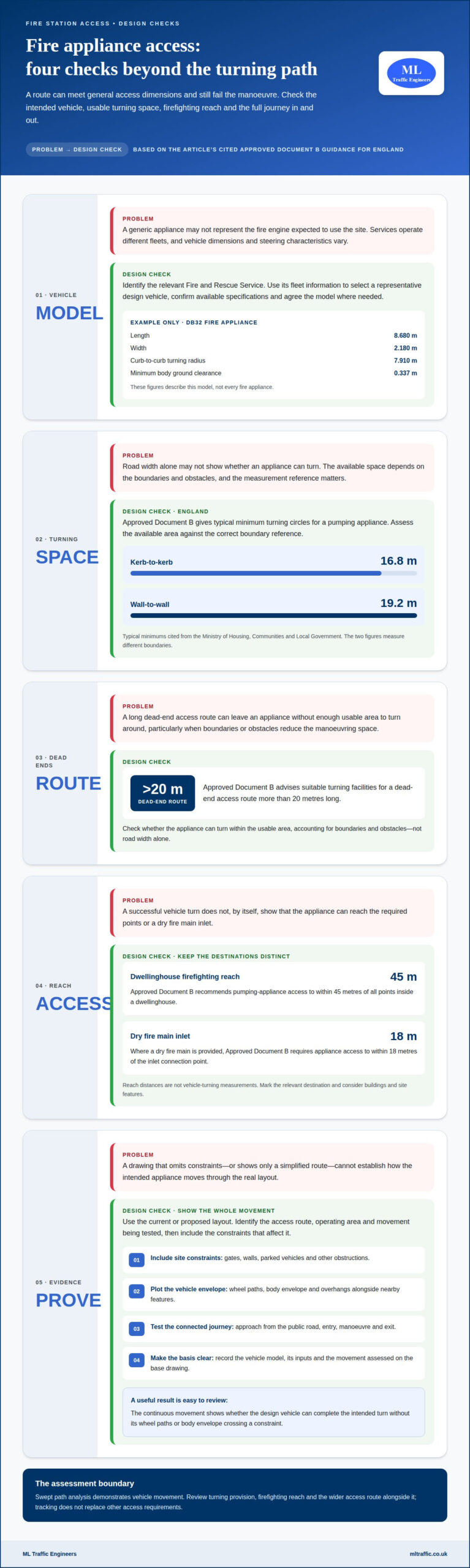
    A fire station can meet general access dimensions and still leave an appliance unable to manoeuvre safely around its own site. Swept path analysis for fire appliances tests how a specified vehicle moves through the proposed layout, including its turning circle and clearance from walls and other constraints. In England, Approved Document B gives typical minimum turning circles for a pumping appliance of 16.8 metres kerb-to-kerb and 19.2 metres wall-to-wall, according to the Ministry of Housing, Communities and Local Government.

    Those figures provide useful context, but the vehicle selected for the assessment matters. Fire and Rescue Services operate different fleets, so a generic appliance may not represent the vehicle expected to use the site. Fire station layouts also need to work in practice, with access and turning movements considered alongside buildings, boundaries and operating arrangements.

    This guide explains how vehicle specifications, tender dimensions, turning radius and accurate base drawings shape a reliable assessment. It also covers wider fire access considerations and checks that help establish whether a fire station layout accommodates its intended appliance.

    Key Takeaways

    • Use vehicle inputs that reflect the appliance expected to serve the site, so the manoeuvre assessment represents real operating conditions.
    • Review tender dimensions and turning characteristics together; a vehicle’s length alone won’t show whether a route is workable.
    • Base the tracking on accurate drawings, since unmeasured boundaries can limit what the assessment establishes.
    • Assess access constraints beyond vehicle movement, including headroom, gradients, loading capacity and pedestrian safety.
    • Test the fire station’s intended layout, including parking and potential obstructions, to understand how they affect appliance access and turning.

    Confirming vehicle specifications with the relevant service

    Start by identifying the Fire and Rescue Service expected to use the site. There is no single standard fire appliance across England, as services operate different fleets. A generic vehicle model can therefore produce a misleading result, even when the drawing looks technically complete. The design vehicle should represent the appliance relevant to the proposal, with its dimensions and steering characteristics recorded as model inputs.

    Scope the tracking assessment around the site and the manoeuvre being tested. Provide the current or proposed layout drawing, identify the access route and operating area, and describe the movement to assess. Include gates, walls, parked vehicles and other constraints. This allows the assessment to test entry, turning and exit against the actual layout, rather than a simplified route.

    How do fire appliance swept paths differ from those of refuse vehicles and other emergency vehicles? Each vehicle type has its own dimensions, steering behaviour and overhangs, so its wheel paths and body envelope can differ. A refuse vehicle or ambulance model should not stand in for a fire appliance. Select a vehicle that matches the movement being assessed.

    Choose a representative design vehicle using the relevant service’s fleet information and the proposal’s operational needs. Available specifications should be confirmed, and agreement with the service may be needed. For example, the DB32 Fire Appliance used in a Carnegie Library assessment is 8.680 m long and 2.180 m wide, with a curb-to-curb turning radius of 7.910 m. Those figures describe that model, not every fire appliance.

    When is fire appliance swept path analysis required for UK planning or building control approval? Use it to demonstrate that the proposed access arrangement accommodates the intended appliance, particularly where turns, restricted spaces or site constraints make movement difficult to judge from dimensions alone. It shows vehicle movement, but does not replace consideration of other access requirements.

    How do local fire and rescue services assess fire appliance access, and how do requirements vary across the UK? Services consider whether the selected appliance can use the proposed route and manoeuvre within the site. Fleet specifications and local expectations vary, so use the relevant service’s vehicle information to guide model selection and any agreement needed.

    A useful report identifies the vehicle model and its inputs, then presents the manoeuvre clearly on the base drawing. It should show wheel paths, the body envelope and overhangs alongside nearby walls, gates and other obstructions. A continuous movement through the route makes clear whether the design vehicle can complete the intended turn without crossing a constraint.

    Clearance is assessed by comparing those vehicle envelopes with the drawn site features. The DB32 Fire Appliance’s minimum body ground clearance is 0.337 m, an example of why vehicle properties matter when assessing changes in level. Record the model inputs and the movement tested so reviewers can understand what the drawing demonstrates and how it relates to the proposed layout.

    Other fire access considerations beyond vehicle tracking

    Vehicle tracking tests movement, but Approved Document B also addresses turning provision, firefighting reach and the wider access route. Review the whole layout against these requirements as well as the vehicle’s path.

    Turning Circles and Dead-End Routes

    Approved Document B gives a typical minimum kerb-to-kerb turning circle of 16.8 metres for a pumping appliance in England, according to the Ministry of Housing, Communities and Local Government. It gives a typical minimum wall-to-wall turning circle of 19.2 metres for the same appliance. These measure different boundaries, so assess the available space using the relevant reference points.

    For a dead-end access route more than 20 metres long, Approved Document B advises suitable turning facilities. Check whether the appliance can turn within the usable area, accounting for boundaries and obstacles rather than relying on road width alone.

    Firefighting Access Distance

    Approved Document B recommends access for a pumping appliance to within 45 metres of all points inside a dwellinghouse. This is a reach consideration, not a vehicle-turning measurement. Assess the route from the appliance’s standing position to the relevant parts of the dwelling, including whether buildings or site features affect that access.

    Where a dry fire main is provided, Approved Document B requires pumping-appliance access to within 18 metres of the inlet connection point. Treat the inlet as a specific destination on the access plan, rather than assuming that proximity to the building is sufficient.

    Emergency Vehicle Access and Egress

    Access and egress need to work as connected movements. Check the approach from the public road, the manoeuvre into the site, and the route back out. The Seeds Lane, Brownhills fire tender drawing provides a practical example: it was prepared on J Mason Associates Ltd Drawing 2427-01D, at 1:200 on A3, and dated 05/2020.

    The drawing scale gives reviewers a defined plan context for assessing the plotted route. The key question is whether the intended vehicle can enter, manoeuvre and leave without its wheel paths or body envelope crossing an obstacle. Account for parked vehicles where a narrow road forms part of the route.

    Which UK standards and guidance apply to fire appliance access and swept path analysis? In England, Approved Document B sets out guidance for access provisions, including turning circles and firefighting distances. Local fire and rescue services may also have requirements shaped by their appliance fleets and access needs.

    Common layout problems include restricted turning space, blocked routes and insufficient reach to a building or dry fire main inlet. The drawing can reveal where the layout constrains movement. Possible design changes include adjusting the access arrangement or removing an obstruction from the tested route.

    For a closer look at how vehicle tracking drawings support planning applications, explore this practical guide to swept path analysis.

    Fire tender dimensions and turning radius

    Vehicle dimensions determine whether a fire tender can pass through an access route and complete its manoeuvre. A useful assessment considers overall length and width alongside steering behaviour, track width, body height and overhangs. Consider the inputs together: a vehicle that fits on a straight approach may still need more room to turn.

    The Fire Tender used in one swept path assessment measures 7.35 metres long and 2.43 metres wide. Its kerb-to-kerb turning radius is 7.1 metres. These figures illustrate how the vehicle’s envelope and steering characteristics inform the drawing. They describe that Fire Tender, so they should not be treated as dimensions for every appliance.

    Turning radius and turning circle describe related but different measurements. A radius measures from the turning centre to a path, while a circle describes the space needed for a complete turn. The tracked wheel paths and body envelope show how the vehicle occupies the available space. On a constrained site, compare those paths with the actual boundaries and obstacles.

    Length and width alone don’t capture every part of a turning movement. Track width affects the wheel paths, while front and rear overhangs can extend beyond them. For example, the DB32 Fire Appliance has a maximum track width of 2.121 metres. The model input should reflect the appliance being assessed, rather than substituting a different vehicle’s steering or dimensions.

    Height matters along the route, not just at the site entrance. Approved Document B gives a typical minimum vertical clearance of 3.7 metres for a pumping appliance in England, according to the Ministry of Housing, Communities and Local Government. Compare that access provision with overhead constraints shown on the layout, including structures that intersect the appliance’s route.

    For context, the DB32 Fire Appliance used in the Carnegie Library swept path analysis has an overall body height of 3.452 metres. That vehicle-specific dimension helps explain why the selected model matters, but it does not replace assessment of route clearance. Record the appliance inputs clearly so a reviewer can distinguish the vehicle’s dimensions from the access criteria being considered.

    Aerial appliances also need vehicle-specific treatment. The cited aerial appliance boom overhang does not exceed 1.83 metres from the vehicle’s foremost part. Include relevant overhangs in the tracked envelope, especially where a turn brings the vehicle close to a wall, gate or building. Reviewing wheel paths and body clearance together makes the manoeuvre easier to assess.

    Use the relevant service’s appliance specification, then test the intended route with those dimensions and steering inputs. The resulting drawing should show whether the vehicle can make its movements within the available space. A radius value alone cannot describe every part of the movement; the complete tracked envelope provides the spatial check.

    Swept Path Analysis for Fire Appliance Access

    Base drawing accuracy and boundary limitations

    A vehicle tracking result is only as dependable as the base drawing used to plot it. The drawing positions roads, buildings, gates and other constraints against the vehicle’s movement. If a boundary is incorrectly positioned, the plotted clearance may look greater or smaller than the actual clearance. Accurate base drawings are essential, and the test does not establish the position of an unmeasured boundary.

    Start by identifying the drawing used for the assessment and its revision. The Seeds Lane, Brownhills analysis was conducted on J Mason Associates Ltd Drawing 2427-01D. That identifier gives the reader a defined plan reference. A drawing number alone, however, doesn’t show whether later site changes have been incorporated. The assessment should relate to the layout being considered, not an earlier arrangement.

    Check that the plan shows the access route and the physical features that constrain movement. For a fire appliance, these could include the road edge, walls, gate positions, building corners and other fixed obstacles. Compare the route shown with the intended entry, turning and exit movements. If a feature is absent or misplaced, the vehicle path cannot reliably demonstrate clearance from it.

    Scale also affects how reviewers interpret a drawing. The Seeds Lane, Brownhills swept path drawing is at 1:200 on A3. This identifies its printed scale and sheet size, but a resized or reproduced copy may not retain that scale. Read the drawing’s dimensions and labels alongside its graphic representation. Don’t rely on measuring a displayed image when its print or screen size may have changed.

    Boundary evidence deserves particular care. A line on a plan may represent a title boundary, fence, wall or surveyed feature, and these are not necessarily the same physical edge. Where a boundary has not been measured, the tracking test cannot determine its precise position. Read the result as movement against the boundary shown, not as proof of clearance from an unseen or unverified feature.

    A practical review follows a clear sequence: confirm the drawing reference, check the layout features, then trace the vehicle movement against them. For example, if a gate appears on the base plan, examine the vehicle envelope at the gate during entry and exit. If the drawing omits a wall beside the gate, the plotted path cannot establish clearance from it.

    Clear, traceable drawings help distinguish a vehicle-movement issue from a base-plan limitation. Keep the drawing reference visible with the assessment, and make sure the features being tested are identifiable. For Seeds Lane, 2427-01D, 1:200 and A3 provide specific references for the plotted analysis. The boundary limitation remains important: vehicle tracking tests the geometry presented, not the location of unmeasured site features.

    Swept path analysis for fire stations

    A fire station assessment should test how appliances move through the whole operating layout, not just whether they can enter the site. Show turning movements, wheel paths and the body envelope, including overhangs, in relation to buildings, walls, gates and other constraints.

    Start with the movements the station needs to accommodate. Plot the approach, entry, circulation, turning and exit routes, then consider how vehicles reach operational areas. A layout that allows one appliance to enter may still restrict another movement if parked vehicles, gates or building corners narrow the usable space.

    Turning provision is a key check. Turning provision is a key check, and the space required depends on the appliance and layout being assessed. For a 32-metre turntable ladder, London Fire Brigade specifies a minimum sweep circle between walls of 19.5 metres. These vehicle-specific examples show why a station assessment should use the intended appliance.

    Test the operating layout as it will be used, including occupied parking bays. A drawing with every bay empty can conceal a pinch point that appears when vehicles are parked. Include parked vehicles on narrow-road approaches, too. The tracked appliance should move continuously through each manoeuvre, without corners or breaks in tyre or overhang trajectories.

    Review both the swept wheel paths and the vehicle body envelope. A wheel path may clear a wall while an overhang approaches a gate or building. Show the vehicle’s turning movements and overhangs, and identify obstacles along the route. This makes the relationship between the simulated movement and site constraints clear to reviewers.

    Consider more than the main appliance bay. Emergency vehicle tracking simulations can test access and egress at fire stations, hospitals and NHS trust sites, and assess whether training facilities accommodate worst-case turning requirements. Swept path analysis has also informed new fire station and emergency service developments for Greater Manchester Fire Authorities.

    Assess each movement against the station’s actual operating arrangement. For example, a route used for both appliance access and parking needs testing with the parking layout represented. Show how the appliance enters, turns and leaves, then review whether its complete envelope remains clear of the constraints shown on the plan.

    The practical takeaway is to assess the station as an occupied, working site. Use the appropriate appliance, plot its complete movement, and include parking and fixed constraints. If your fire station layout needs a clear vehicle-tracking assessment, arrange swept path analysis for the proposed movements.

    ML Traffic Engineers UK: Swept Path Analysis

    ML Traffic Engineers UK provides Swept Path Analysis for development proposals where fire appliance access or manoeuvring needs to be demonstrated. Use the service when a site layout includes constrained turns, narrow approaches, gates, parking or other features that may affect vehicle movement.

    The assessment plots the selected vehicle’s movement against the proposed layout, showing wheel paths, body envelope and clearance from site constraints. Accurate drawings and representative vehicle inputs are central to a useful result. Where the wider planning submission needs supporting transport documentation, Transport Statements or Transport Assessments may also be relevant.

    Contact ML Traffic Engineers UK to discuss Swept Path Analysis for your proposed layout.

    Make fire access part of the next design decision

    Plan fire appliance access as the site layout develops, not as a final drawing exercise. A well-timed swept path analysis for fire appliances can inform layout decisions while there is still room to adjust circulation, parking and operational areas. That helps the design team consider vehicle movement alongside the site’s wider planning requirements.

    ML Traffic Engineers UK provides Swept Path Analysis, Transport Statements and Parking Surveys to support development proposals. The right documentation depends on the questions the project needs to answer, from appliance manoeuvring to transport impacts and parking provision.

    If your proposal needs a clear assessment of fire appliance movement, take the next step and contact ML Traffic Engineers UK to discuss the project. A considered approach can help move the layout forward with greater clarity and confidence.

    Frequently Asked Questions

    What is swept path analysis for fire appliances?

    Swept path analysis for fire appliances is a vehicle-tracking assessment that plots how a selected fire appliance moves through a proposed route or site. It helps assess whether the vehicle can make the intended manoeuvre within the available space. For example, a development team can use the drawing to examine a tight entrance before fixing its position, then see whether a revised layout changes the vehicle’s route.

    What design vehicle dimensions and turning characteristics should be used for a UK fire appliance?

    Use dimensions and steering inputs for an appliance representative of the vehicle expected to use the site. Fire and Rescue Services operate different fleets, so the appropriate model depends on the proposal and relevant service information. Inputs should describe the vehicle’s overall dimensions, wheel paths and turning behaviour, with overhangs represented where relevant. This avoids treating a single example vehicle as a universal UK design standard.

    What minimum road widths, turning radii and headroom are required for fire appliance access in the UK?

    In England, Approved Document B gives a typical minimum road width of 3.7 metres and vertical clearance of 3.7 metres for a pumping appliance. Approved Document B gives typical minimum turning circles of 16.8 metres kerb-to-kerb and 19.2 metres wall-to-wall, according to the Ministry of Housing, Communities and Local Government. These are distinct measurements, so assess the relevant route geometry and overhead constraints together.

    How is fire appliance swept path analysis carried out using CAD or vehicle-tracking software?

    The analyst places the selected vehicle model on a scaled site drawing, then simulates the required movements through the layout. The output plots wheel trajectories and the vehicle envelope for review against site features. For a CAD drawing to communicate the result clearly, it should identify the vehicle inputs and show the movement being tested. Reviewers can then see which manoeuvre the tracking demonstrates and where constraints affect it.

    Michael Lee

    Article by

    Michael Lee

    Transport planner with over 35 years' experience.

    Disclaimer

    The content on mltraffic.co.uk, including all technical articles, guides, and resources, is provided for general informational and educational purposes only. It is not intended to constitute professional advice in traffic engineering, transportation planning, development approvals, or any other technical or legal field.
    While ML Traffic Engineers makes every reasonable effort to ensure the accuracy, completeness, and timeliness of the information published, we do not provide any warranties or representations (express or implied) regarding its reliability, suitability, or availability for any particular purpose. Any reliance you place on the content is strictly at your own risk.
    In no event shall ML Traffic Engineers, its directors, employees, authors, or affiliates be liable for any direct, indirect, incidental, special, consequential, or punitive damages (including, without limitation, loss of profits, data, or business opportunities) arising out of or in connection with the use of, or inability to use, any information provided on this website.
    The articles and guides on this site are not a substitute for engaging a qualified, professional traffic engineer to assess your specific project requirements. For tailored advice, compliance assessments, or traffic engineering services, please contact a competent professional.
    This disclaimer may be updated from time to time without notice. By accessing or using this website, you agree to be bound by the most current version of this disclaimer.
  • Swept Path Analysis for Residential Driveway Access in the UK

    Swept Path Analysis for Residential Driveway Access in the UK

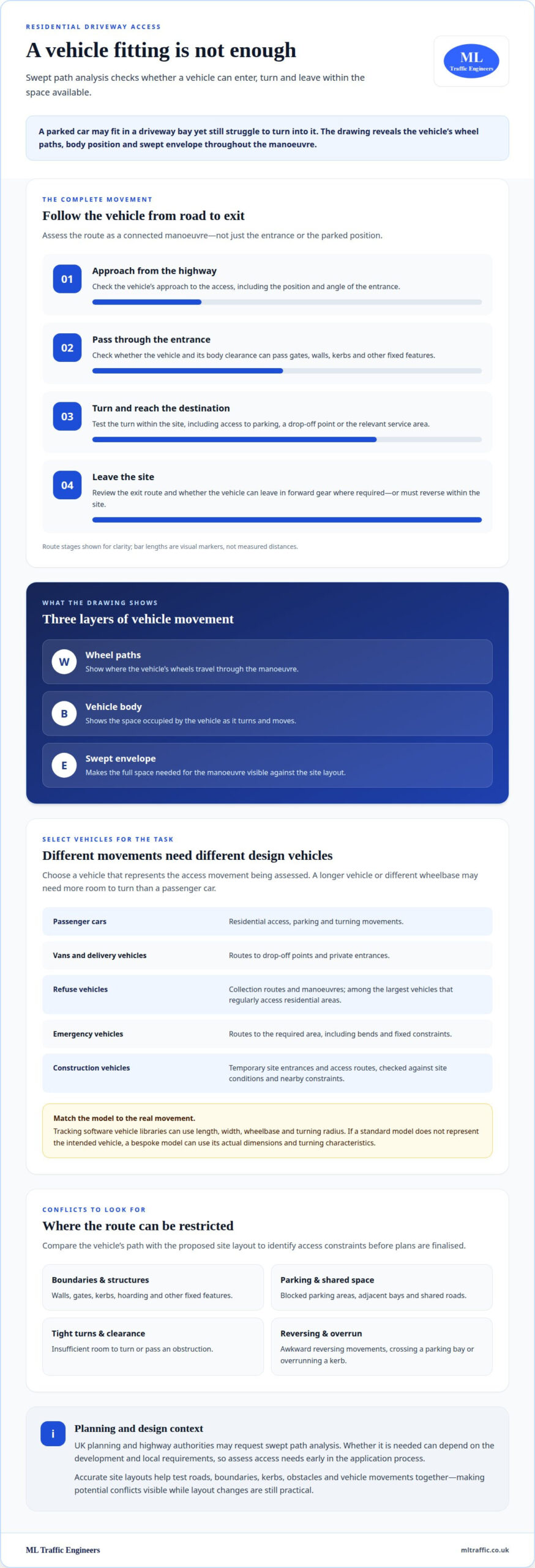
    A driveway’s usable width is only part of the picture. Swept path analysis for residential driveways models how a vehicle enters, turns and exits, showing its wheel paths and the space its body occupies. This can reveal whether walls, gates, kerbs or other features restrict the manoeuvre.

    It is easy to focus on whether a car fits when parked, but access also depends on whether it can pass through the entrance and turn within the available space. Larger service vehicles may also need to be considered, depending on the development and the movements being assessed.

    This guide explains what a swept path drawing shows, how analysis supports driveway and development access, and what planning authorities may request in the UK. It also covers the information needed to model movements, the role of specialist software and how findings can inform layout changes before plans are finalised.

    Key Takeaways

    • A swept path drawing shows more than whether a vehicle fits: it maps wheel paths, body position and the space needed through a manoeuvre.
    • Choose the design vehicle and manoeuvre to match the access being assessed, including service or emergency vehicle movements where relevant.
    • Accurate site layouts help reveal potential conflicts with gates, walls, kerbs, parking and other fixed features before plans are finalised.
    • Planning authority requests can depend on the development and local requirements, so assess access needs early in the application process.
    • Specialist tracking software models vehicle movements, while swept path analysis can support driveway design and planning documentation.

    What is a Swept Path Analysis?

    A swept path analysis models a vehicle’s movement through a site using its dimensions and turning characteristics. For residential access, it can show whether selected vehicles can enter, manoeuvre and leave without conflicting with the layout.

    Emergency Vehicle Access

    For emergency access, the analysis tests a selected emergency vehicle’s route through the site. It can show whether the vehicle can reach the required area, negotiate bends and clear fixed features such as walls, gates and parked vehicles.

    Review the entire manoeuvre, not just the entrance. A drawing can illustrate forward and reverse movements, including whether the vehicle can leave in forward gear or must reverse. This helps identify tight turns and obstructions that may affect access.

    For example, a proposed driveway might admit a car but constrain a larger emergency vehicle at a boundary wall. Modelling both movements makes the difference clear on the plan, so the access layout can be reviewed before it is finalised.

    Delivery and Refuse Vehicle Access

    Delivery and servicing movements can be tested against the driveway, parking area and route through the site. The vehicle’s turning path shows whether it can reach a drop-off point, turn around or leave without crossing into a wall, gate or neighbouring space.

    Refuse vehicles need particular consideration because they are among the largest vehicles that regularly access residential areas. The appropriate design vehicle depends on the development and movement being assessed. A refuse collection route may require a different manoeuvre from a delivery van reaching a private entrance.

    Check the approach, turning area and exit together. A vehicle may enter successfully but need an impractical reversing movement to leave. The drawing can highlight this constraint and show where the layout restricts vehicle movement.

    Vehicle Selection and Dimensions

    Choose vehicle types to match the access task. Depending on project requirements and available information, residential assessments may model passenger cars, vans, rigid delivery vehicles, refuse vehicles or construction vehicles. The selected design vehicle should represent the movement the layout needs to accommodate.

    Vehicle libraries in tracking software provide models with dimensions such as length, width, wheelbase and turning radius. These inputs affect the path: a longer vehicle or a different wheelbase may need more room to turn than a passenger car. The drawing typically shows wheel paths, the vehicle body and its swept envelope.

    If a standard library model does not represent the intended vehicle, a bespoke model can use its actual dimensions and turning characteristics. This makes the simulation specific to the vehicle being assessed. For swept path analysis for residential driveways, matching the vehicle and manoeuvre to the real access task is essential for a useful result.

    Residential driveway and development access

    Access assessment follows each vehicle from the public highway into the site, through its manoeuvre and back out. Common problems include tight turns, insufficient clearance from boundaries, blocked parking areas and layouts that leave vehicles needing awkward reversing movements.

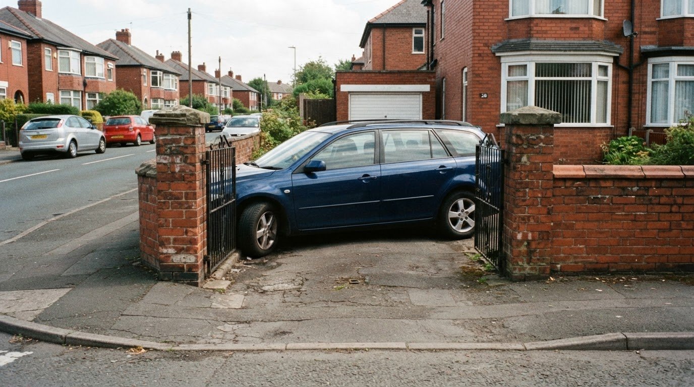
    These issues can be difficult to spot on a plan that shows only fixed parking spaces. A swept path drawing shows the vehicle’s route and occupied space, helping identify where a gate, wall, parked car or kerb interferes with turning. For example, a car may fit in a driveway bay but struggle to turn into it.

    Assess the whole movement, not just the entrance. Test the approach from the highway, the access position and angle, movement within the site and the exit route. Check whether the selected vehicle can enter and leave in forward gear where required, and whether any reversing takes place within the site.

    For a residential layout, examine how driveways interact with shared roads, parking spaces and turning areas. In custom home architecture and neighborhood planning, firms like TanneyDesign coordinate these elements early so that site layouts balance aesthetics with functional vehicular movement. A vehicle tracking path can reveal whether a car needs to cross an adjacent parking bay or overrun a kerb to complete a turn. The drawing can also show whether an obstruction narrows the usable route.

    Development access may need to serve more than residents’ cars. Test delivery vans reaching drop-off points, servicing vehicles approaching their working area and refuse vehicles following the intended collection route. Each movement may have a different destination and turning requirement, so assess them against the actual site layout.

    Construction-phase access raises a separate design question. Temporary access roads and site entrances may need to accommodate construction vehicles as site conditions change. Model the intended route against gates, hoarding, kerbs and nearby highway constraints. If a vehicle cannot complete the planned turn, the access alignment or working layout may need to change.

    Emergency access also depends on the route beyond the entrance. Assess whether the selected vehicle can reach the relevant part of the development, negotiate bends and pass fixed constraints. A clear route on the site plan is not enough if the vehicle’s turning path conflicts with a wall or parked vehicle.

    Start with an accurate site or layout drawing showing roads, boundaries, kerbs and obstacles. Then define the vehicle and manoeuvre to test, including entry, turning, stopping or exit. Comparing these movements with the proposed layout makes specific access conflicts visible while design changes are still practical.

    For a closer look at how vehicle movements are illustrated for planning, the AutoTURN swept path analysis guide explains the role of tracking drawings in assessing access arrangements.

    Planning authority requirements in the UK

    UK planning and highway authorities may request swept path analysis when a proposal changes vehicle access or movement. A highway authority can ask for it while determining a planning application, making vehicle tracking relevant to the evidence submitted with the application.

    To commission an analysis, provide an accurate site or layout drawing showing the access, roads, kerbs, obstacles and other relevant features. Include the vehicle type and manoeuvre to be tested, such as entering, turning, reversing or exiting. Plans can be supplied in PDF or CAD format.

    Requirements depend on the development, expected vehicle movements and the local authority’s assessment of access. A drawing may need to demonstrate that vehicles can reach parking, turn within the site or leave safely. Showing the proposed entrance alone may not establish whether the full route works.

    For example, a house proposal with a narrow entrance and a turning area near a boundary may need to show how a vehicle moves between them. Planned or likely on-street parking can also affect the space available on an approach. Include these conditions in the assessment when they are relevant to the proposed movement.

    The evidence should make each tested manoeuvre clear. A swept path drawing can show the vehicle body, wheel paths and swept envelope against the proposed layout. Review the entrance, internal turn and exit as separate stages, then assess clearance from fixed features and interaction with parked vehicles.

    Local highway guidance may also address how larger vehicles manoeuvre on narrow roads and the visibility needed near bends or junctions. Where relevant, the submitted layout should show how the access arrangement relates to the surrounding highway. The authority’s requirements shape the evidence expected for the site.

    Before submitting an application, allow the relevant highway authority to assess the proposed layout where its input is needed. Considering access early can bring questions into the design process before the application is determined, when layout changes may be easier to incorporate.

    Use the analysis to address conflicts shown on the plan. A constrained entrance, obstructed turning area or limited clearance may call for a revised access position, parking arrangement or layout. Accurate drawings and clearly defined vehicle movements help the authority assess how the proposal works in practice.

    Software used for swept path analysis

    Swept path software models a selected vehicle moving through a site layout. It uses vehicle dimensions, turning characteristics and the intended manoeuvre to create a visual path. For residential access, this can show how a car or service vehicle interacts with parking, gates, kerbs and walls.

    Specialised software can be used to model vehicle movements for swept path analysis. These tools can simulate forward and reverse movements. The analyst selects the vehicle, loads the site layout and defines the route to test. The resulting path can then be reviewed against the proposed access geometry.

    Software matters, but the input drawing matters just as much. A CAD layout can provide geometry for roads, parking spaces, kerbs and fixed obstacles. The analyst uses this information to position the vehicle path accurately. If the drawing omits a wall or shows an incorrect access width, the output may not represent the actual layout.

    Browser-based tools offer one way to access a modelling workflow, while CAD-based processes work directly with design drawings. The practical choice depends on the source layout, required output and how the vehicle movements need to be presented. Whichever approach is used, the model must reflect the intended vehicle and manoeuvre.

    For example, testing a car entering a driveway differs from testing a refuse vehicle turning within a shared access. Each movement needs its own route and vehicle model. The analysis should also account for whether the vehicle travels forwards, reverses or changes direction near a parking space. A clearly defined test setup makes the result easier to interpret.

    A useful report turns the simulation into evidence that can be reviewed alongside the design. Visuals can show the vehicle path against the layout, making tight corners and potential conflicts easier to identify. The drawing typically presents the wheel paths, vehicle body position and swept envelope, rather than relying on a written description alone.

    Before interpreting a software output, check that the site drawing shows the relevant access features and that the selected vehicle suits the movement. Then review the path for clearance from boundaries and other fixed features. For a planning submission, the drawing should make the tested route and any constrained manoeuvre clear to the person reviewing the proposal.

    Software alone cannot determine whether a layout works. It provides a model for assessing vehicle movement. Its value depends on pairing accurate geometry with an appropriate vehicle, clearly defined movements and a report that relates the simulation to the proposed design.

    Swept Path Analysis for Residential Driveway Access in the UK

    Swept path analysis in civil engineering

    In civil engineering, vehicle tracking connects transport needs with the geometry of a proposed site. It tests whether a design vehicle’s movement fits the physical layout, helping engineers assess how access roads, junctions and parking areas work together.

    The analysis can inform geometric design decisions, not simply confirm whether a vehicle can turn. For example, a tracked path may show that a kerb alignment or junction corner restricts movement. Designers can then assess layout changes before fixing road markings, parking bays or access positions.

    Horizontal tracking examines a vehicle’s path across the plan, but a driveway also has a vertical profile and cross-sections. Gradients, changes in level and surface shape can affect vehicle clearance, so a two-dimensional turning plan may not show every potential conflict.

    Three-dimensional CAD swept path simulations can test vehicle movement against driveway surfaces and terrain. They can identify vehicle-terrain conflicts that two-dimensional driveway profile analysis does not reveal. This matters where a vehicle crosses a steep transition or uneven surface rather than turning across a flat paved area.

    For engineering projects, the design vehicle and geometry must be considered together. The vehicle’s dimensions and turning characteristics shape its path; the site’s alignment, profile and cross-sections shape the available space. Testing these elements in a coordinated model gives a more complete view of how the design performs.

    A practical review can follow a clear sequence. First, establish the design layout and relevant ground levels. Then model the vehicle’s intended route across that geometry. Finally, inspect the path for conflicts with kerbs, boundaries, surface changes and other fixed features. This helps distinguish a plan-view constraint from a terrain-related issue.

    These findings can guide discussions across civil engineering and transport planning. A tight turning path might require a revised access alignment; a ground-clearance conflict may call for changes to the driveway profile. The appropriate response depends on where the model shows the vehicle contacting or overrunning the proposed geometry.

    The key is to match vehicle tracking to the engineering question. A two-dimensional model can assess horizontal movement, while three-dimensional analysis can examine how vehicle paths interact with surface geometry. Where driveway levels or terrain matter, consider the full three-dimensional relationship before finalising the design.

    Explore the vehicle tracking workflow for planning projects to see how movement analysis can support design decisions.

    ML Traffic Engineers UK: Transport Statements

    ML Traffic Engineers UK provides Swept Path Analysis to assess vehicle access and manoeuvring for residential layouts. Use the service when a proposed driveway, parking arrangement or access route needs a clear vehicle-tracking assessment for design or planning evidence.

    Where a wider planning submission needs transport documentation, Transport Statements and Transport Assessments can address the development’s transport considerations. Parking Surveys can provide evidence about parking conditions relevant to a proposal. The appropriate work depends on the planning question and the information needed to assess the site.

    To discuss your project or find out more, visit ML Traffic Engineers UK.

    Move your access design forward

    A driveway layout is easier to refine while the design is still taking shape. Use swept path analysis for residential driveways to guide discussions with your design team, especially when vehicle movement affects the entrance, parking arrangement or available turning space. Clear access evidence keeps transport considerations connected to the site layout as plans progress.

    ML Traffic Engineers UK provides Swept Path Analysis, alongside Transport Statements and Parking Surveys to support related planning work. The next step depends on the evidence your proposal needs and the access question you need to resolve.

    Bring your access requirements into focus and discuss the appropriate transport planning support. Contact ML Traffic Engineers UK to explore the next step for your project.

    With a clear assessment, you can move your driveway plans forward with greater confidence.

    Frequently Asked Questions

    What Vehicles Can Be Assessed?

    A swept path assessment can model passenger cars, vans, rigid delivery vehicles, refuse vehicles and construction vehicles. Emergency vehicles can also be assessed when their access forms part of the design question. For example, a proposal with a shared access might test a resident’s car alongside the vehicle expected to serve the site. Select vehicles according to the project’s actual use and the movements the layout needs to accommodate.

    What is swept path analysis for a residential driveway?

    It is a computer-based assessment of how a chosen vehicle moves through a driveway or site. The analysis maps the vehicle’s movement so a designer can see whether the proposed arrangement accommodates the intended journey. For a house, that might mean testing a car entering from the street, reaching a parking space and turning to leave. It assesses movement, not simply the dimensions of a parked vehicle.

    When is swept path analysis required for a UK house or driveway planning application?

    It may be requested when a proposal changes access, parking or vehicle movements and the planning or highway authority needs evidence that the layout is workable. A new house access, altered driveway or development with shared vehicle routes can prompt an assessment. The need depends on the proposal and the authority’s concerns. If an application includes a constrained entrance or turning area, showing vehicle movements in the submitted design can help clarify access.

    Which vehicle types and design vehicles should be used for residential driveway swept path analysis?

    Choose design vehicles that reflect who will use the site and which movements need testing. A single-home access may focus on a passenger car, while shared residential layouts can also involve delivery or refuse collection movements. Consider emergency access when it forms part of the assessment. The vehicle model should represent the relevant vehicle’s dimensions and turning characteristics, rather than simply selecting the largest available model.

    What UK standards and guidance cover driveway access widths, turning areas and vehicle tracking?

    Driveway access is assessed against the planning and highway considerations relevant to the project and location. Requirements can depend on the road context, proposed layout, vehicle movements and local authority guidance. A tracking drawing tests how the selected vehicle moves through the design, but does not establish every applicable design requirement by itself. Consider the authority’s expectations alongside the layout, particularly where access meets a public highway.

    How is a driveway swept path analysis carried out using CAD or vehicle tracking software?

    The analyst works from a site or design plan and sets up the vehicle and manoeuvre in tracking software. CAD drawings can provide geometry for the driveway and surrounding features; PDF plans can also form part of the supplied layout information. The model then represents the movement for review. Before relying on the drawing, ensure the plan reflects the design being assessed, including relevant boundaries and obstructions.

    What driveway dimensions and turning space are needed for cars, vans and refuse vehicles?

    There is no single driveway dimension that suits every car, van or refuse vehicle movement. The space required depends on vehicle dimensions, turning characteristics, access alignment and manoeuvre. A vehicle entering straight into a space needs a different layout from one turning around or reversing to exit. Assess the chosen vehicle against the actual plan rather than applying a dimension without considering how the vehicle must move.

    Do driveway access and turning requirements vary by UK council or local planning authority?

    Yes. Local requirements and highway authority expectations can differ, and the assessment also depends on the site and proposed movements. A layout considered in one council area may raise different questions elsewhere, especially where road widths, parking or access arrangements differ. Review the relevant authority’s published expectations for the application area and ensure vehicle tracking reflects the design and movements being submitted.

    Michael Lee

    Article by

    Michael Lee

    Transport planner with over 35 years' experience.

    Disclaimer

    The content on mltraffic.co.uk, including all technical articles, guides, and resources, is provided for general informational and educational purposes only. It is not intended to constitute professional advice in traffic engineering, transportation planning, development approvals, or any other technical or legal field.
    While ML Traffic Engineers makes every reasonable effort to ensure the accuracy, completeness, and timeliness of the information published, we do not provide any warranties or representations (express or implied) regarding its reliability, suitability, or availability for any particular purpose. Any reliance you place on the content is strictly at your own risk.
    In no event shall ML Traffic Engineers, its directors, employees, authors, or affiliates be liable for any direct, indirect, incidental, special, consequential, or punitive damages (including, without limitation, loss of profits, data, or business opportunities) arising out of or in connection with the use of, or inability to use, any information provided on this website.
    The articles and guides on this site are not a substitute for engaging a qualified, professional traffic engineer to assess your specific project requirements. For tailored advice, compliance assessments, or traffic engineering services, please contact a competent professional.
    This disclaimer may be updated from time to time without notice. By accessing or using this website, you agree to be bound by the most current version of this disclaimer.