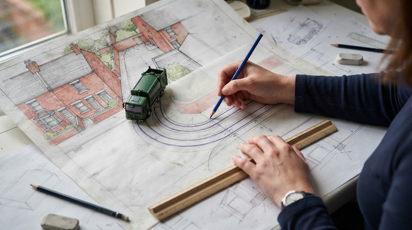
A swept path analysis for an 11.4m local authority refuse collection vehicle can be prepared without CAD by using a scaled plan, the authority-specified vehicle data and a clear record of each manoeuvre. In Bristol, design vehicles will normally include an 11.4 m refuse vehicle and emergency vehicles, so the correct vehicle selection is the starting point.
You don’t need specialist drawing software to make a diagram easy to follow, but you do need a consistent scale and enough detail to show where the vehicle travels. If the drawing omits the swept envelope or makes clearances difficult to judge, reviewers may not have the evidence they need.
This guide explains how to identify the required design vehicle, prepare a scaled base plan and trace the manoeuvre by hand. It also covers how to label the swept envelope, record clearances and present the drawing so its assumptions and limitations are clear. The goal is a practical, transparent diagram that helps assess access before the layout is finalised.
Key Takeaways
- Use the authority’s vehicle requirements to guide your selection, rather than relying on a generic refuse vehicle template.
- Build the manoeuvre around a scaled base plan, tracing the vehicle’s movement through the full access route.
- Make the swept envelope and the relationship to nearby boundaries and obstacles clear on the drawing.
- Label the plan so reviewers can understand its scale, vehicle assumptions and intended route without guessing.
- Learn when a professionally prepared Swept Path Analysis can help resolve access and layout questions.
Choosing the authority-specified design vehicle
Local authorities set access expectations through their transport or waste-collection guidance and development review. Requirements can address vehicle dimensions, gradients, headroom and turning facilities; use the criteria that apply to the site rather than assuming one standard covers every authority.
- Identify the authority responsible for the site. Find the council’s transport, highways or waste-collection guidance, then locate its access and vehicle requirements. Check the documents relevant to the proposed development and note any project-specific instructions. This establishes the design basis before drawing begins and helps avoid relying on an unrelated council’s criteria.
- Record the specified vehicle and its source. Write down the vehicle description exactly as the authority gives it, including any stated length or configuration. For an assessment using an 11.4 m refuse vehicle, record that length alongside the relevant vehicle description. Retain the source document or design instruction in the drawing notes so the selected vehicle can be traced to the project requirements.
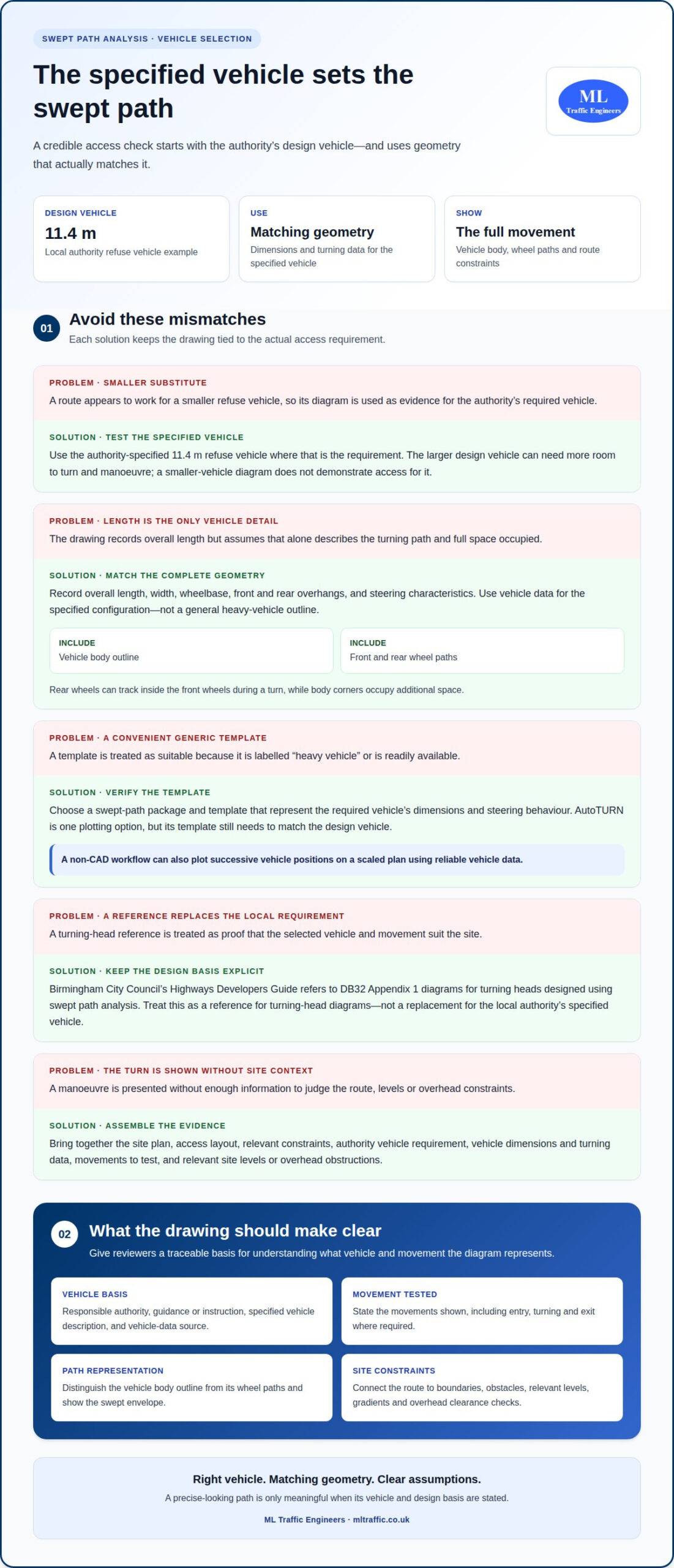
- Use matching vehicle geometry. Obtain dimensions and turning data for the specified vehicle rather than estimating its movement from overall length. Body width, wheelbase, overhangs and steering behaviour affect the space occupied during a manoeuvre. Keep the data source and assumptions with the working drawing. Don’t substitute a smaller or differently configured vehicle simply because its template is easier to obtain.
- Translate access criteria into drawing checks. List the requirements the authority expects the layout to demonstrate, such as route width, gradient changes, overhead clearance and turning space. Link each criterion to the relevant part of the plan or supporting detail. For example, identify where a structure could affect headroom instead of describing the entire route as clear without showing the constraint.
- Resolve differences before tracing the route. Compare the authority’s vehicle description with the available vehicle data. If the stated design vehicle and the available template describe different configurations, retain the authority’s design basis and use matching geometry. Assess gradients and headroom against the site’s levels and constraints; a plan without relevant level information cannot demonstrate those conditions.
- Set out the assumptions transparently. Add the responsible authority, guidance document, vehicle description and data source to the working notes. State which movements the drawing tests, including entry, turning and exit where required. Clear notes make the design basis traceable and help prevent a precise-looking diagram from being mistaken for evidence about another vehicle.
Which vehicle goes on the diagram?
Choose the vehicle that matches the authority’s requirement, then use its geometry to test the route. A swept path analysis for an 11.4m local authority refuse collection vehicle must represent that specified vehicle, not a smaller substitute.
-
Compare refuse vehicle access needs
Compare the authority-specified 11.4 m vehicle with any smaller refuse vehicle proposed for the site. The larger design vehicle can require more space to turn and manoeuvre, so a route that accommodates a smaller vehicle may not suit the specified one. Don’t use a smaller vehicle’s diagram as evidence for access by the required vehicle.
Birmingham City Council’s Highways Developers Guide refers to DB32 Appendix 1 diagrams for turning heads designed using swept path analysis. Treat this as a reference for turning-head diagrams, not a replacement for the local authority’s specified vehicle. Keep the chosen vehicle and movement being tested clear in the drawing notes.
-
Record vehicle dimensions and turning characteristics
Record the selected template’s overall length, width, wheelbase, front and rear overhangs, and steering characteristics. The 11.4 m length alone cannot establish the turning path or the vehicle’s full footprint. These details depend on the vehicle configuration, so use geometry that matches the specified refuse vehicle rather than a general heavy-vehicle outline.
Check that the template shows both the vehicle body and wheel paths. During a turn, rear wheels can track inside the front wheels, while the body’s corners occupy additional space. A swept path analysis for an 11.4m local authority refuse collection vehicle should therefore use complete vehicle geometry when testing a tight entrance, turning head or constrained junction.
-
Select software and vehicle templates
Choose a swept-path package and template that match the authority’s design vehicle. AutoTURN is one option for plotting vehicle movement paths, but its template must still represent the required vehicle’s dimensions and steering behaviour. Don’t assume a generic heavy-vehicle template is equivalent without comparing its geometry.
A non-CAD workflow can plot successive vehicle positions on a scaled plan using reliable vehicle data. Keep the source dimensions with the drawing and distinguish the body outline from the wheel paths. The method may vary, but the selected vehicle and its geometry must remain consistent.
-
Assemble the information for the analysis
Provide the site plan, access layout, relevant constraints and the authority’s vehicle requirement. Include the vehicle’s dimensions and turning data, the movements to test, and any site levels or overhead obstructions that affect the route. This establishes a clear site and vehicle basis, rather than presenting an illustrative turn without stated assumptions.
For a swept path analysis for an 11.4m local authority refuse collection vehicle, keep the movement requirements aligned with the proposed access. This helps the resulting diagram test the route the development will actually rely on.
Documenting and exporting swept-path drawings
- Set a suitable drawing scale. Choose a scale that keeps the route and vehicle envelope legible on the sheet, and follow the receiving UK authority’s drawing requirements. No single scale applies universally to every UK submission. Show the chosen scale on the drawing and use it consistently from the base plan to the exported file.
Add a scale bar as well as a scale note. If someone views or prints the PDF at a different size, the bar helps them interpret distances without relying only on page dimensions.
- Prepare a clear base plan. Show the access route, kerbs, boundaries, buildings and fixed obstacles that affect vehicle movement. Use distinct line weights for site features, vehicle outlines and swept paths. If a gate or narrow access point controls the turn, mark it clearly so reviewers don’t have to infer its position.
Show enough of the approach and exit to explain how the vehicle reaches and leaves the manoeuvre. A drawing cropped tightly around a turning head may hide constraints on the adjoining route.
- Make the movement easy to follow. Distinguish the swept envelope, wheel paths and vehicle body using clear line styles or colours. Add direction arrows for entry, forward travel, reversing and exit. If the vehicle changes direction within a turning area, show the sequence so every part of the manoeuvre is clear.
Where paths overlap, use a small key or distinct line patterns to separate them. Place the key outside the access route so it does not obscure the area being assessed.
- Document the design basis on the sheet. Include the vehicle description, source of its dimensions, drawing scale and movements tested. Identify the local authority’s specified design vehicle where applicable. These notes link the diagram to its assumptions and help prevent it being mistaken for evidence relating to another vehicle.
Keep limitations specific to the drawing. For example, state if it shows the entry movement but not the vehicle’s exit route.
- Inspect the exported file before issue. Export the drawing as a PDF and review it at the intended page size. Confirm that labels are readable, line styles remain distinct, and the scale bar and notes are visible. Compare the PDF with the working drawing to catch clipped text, missing layers or a shifted base plan.
Use a descriptive file name that identifies the site, vehicle and revision. Keep the issued PDF separate from working drafts so the submitted drawing is easy to identify.
Drawing vehicle manoeuvres
Work from the scaled site plan and the selected vehicle geometry. Draw each movement in sequence to show how the refuse vehicle enters, turns and leaves.
- Mark the route and control points. Identify the entrance, kerb lines, turning area and exit on the base plan. Mark any gate, parked-vehicle area, wall or other fixed feature that could affect movement. These control points show where the vehicle must pass and where the manoeuvre needs closer attention.
For example, a narrow entrance followed by a turn means both the approach and the turn must appear on the drawing. Don’t crop the plan to show only the turning head.
- Set the vehicle’s starting position. Place the vehicle on the approach, aligned with the route. Use the front, rear and wheel positions from the selected geometry, not a rough rectangle. The starting position should show how the vehicle reaches the site entrance before steering begins.
Keep the vehicle outline parallel to the approach where the road allows. If the approach curves, show that alignment instead of forcing a straight entry.
- Trace the steering movement in stages. Draw successive vehicle positions through the turn, changing the heading gradually. At each position, retain the full body outline and wheel locations. This shows how the front corners swing outward while the rear wheels follow a different track.
Use enough intermediate positions to make the path clear. An outline only at the start and finish can hide the space occupied between them.
- Include every direction change. Where the route requires forward and reverse movements, show them as separate parts of the manoeuvre. Add direction arrows and distinguish each movement with a clear line style. For a multi-point turn, make the order of forward and reversing movements visible.
Don’t merge overlapping paths into an indistinct mark. Reviewers need to understand which vehicle position belongs to each part of the turn.
- Repeat the tracing for the complete route. Continue from the turn to the site exit, including any change in alignment at a junction or access throat. Check that the final position leads into the intended exit route. A diagram showing entry but not exit leaves the full vehicle movement untested.
If the vehicle passes close to a boundary, keep that feature visible in the drawing. The relationship between the vehicle outline and the site layout is part of the assessment.
- Review the drawing as a sequence. Follow the arrows from approach to departure and confirm that each outline connects logically to the next. Look for gaps in the route, unclear overlaps or a vehicle position that appears to jump across the plan.
Then compare the plotted path with the underlying plan. Misaligned tracing can make a workable route appear clear or conceal a conflict with a kerb, wall or other fixed feature.
Reading swept envelopes and clearances
Compare the envelope with site features to identify where the vehicle comes closest to an obstruction. Assess every part of the route, not just the turning point.
-
Check road widths and turning radii
Compare the swept envelope with the available carriageway and turning area; no single minimum width or turning radius applies to every 11.4 m refuse vehicle and site layout. The required space depends on the selected vehicle’s geometry, steering path, approach angle and nearby boundaries, so assess the authority-specified vehicle on the actual plan.
At a bend, check both the inner rear-wheel path and the outer body swing. Road width alone cannot show whether a vehicle can negotiate a junction or turning head.
-
Identify design failures and safety risks
Trace the full vehicle outline beside kerbs, walls, gates and parked-car areas. Common design failures include a rear wheel crossing a kerb, a front corner clipping a boundary, or the body overhanging a pedestrian route. A turning diagram can also reveal a route that relies on reversing when the layout assumes forward movement.
Review each conflict in context. An envelope crossing a fixed obstruction indicates a geometric conflict; overlap with a pedestrian area highlights a potential interface that needs design attention.
- Read the full envelope, not only the wheel tracks. Wheel paths show where the tyres travel, while the body outline captures front and rear overhang. Compare both with the plan. For example, the rear wheels may clear a kerb while a front corner swings towards a wall.
Check every plotted vehicle position throughout the manoeuvre. A clear starting and finishing position does not prove the space between them is clear.
- Assess clearances at the tightest points. Locate the narrowest gap between the envelope and a fixed feature, such as a gatepost or building corner. Make sure the scale and linework let readers distinguish a genuine gap from contact or overlap. Keep the relevant feature visible on the plan.
If the plan includes a height constraint, assess overhead clearance separately from the horizontal envelope. A plan view alone cannot demonstrate clearance beneath a canopy or overhang.
- Record conflicts and refine the layout. Mark each pinch point and identify the vehicle movement that creates it. Then test a layout change, such as adjusting a kerb line or turning area, against the same vehicle path. Keep the revised drawing and its assumptions clear so the comparison shows what changed.
For a project-specific review of vehicle paths and site clearances, request a swept path analysis based on the proposed layout and design vehicle.
ML Traffic Engineers UK: Swept Path Analysis
ML Traffic Engineers UK provides Swept Path Analysis to assess whether a proposed site layout accommodates the authority-specified refuse vehicle. Use the service when an access route, turning head or constrained entrance needs a clear, documented assessment of vehicle movements.
The analysis shows the vehicle path against the site layout, helping identify potential conflicts with boundaries, kerbs and other fixed features. Provide the site plan and vehicle requirement so the assessment addresses the intended access movements. If the planning submission also needs transport documentation, a Transport Statement or Transport Assessment may support the project.
Contact ML Traffic Engineers UK to discuss Swept Path Analysis for your proposed layout.
Move your access design forward
A clear swept path analysis for an 11.4m local authority refuse collection vehicle can help you address vehicle access while the site layout is still being developed. The next step is to relate the movement assessment to the planning information your project needs, so access constraints can inform design decisions and supporting documentation.
ML Traffic Engineers UK provides Swept Path Analysis, alongside Transport Statements and Parking Surveys where they fit the project’s requirements. Each addresses a different transport-planning need, helping provide relevant evidence for a development proposal.
Share your proposed layout and authority vehicle requirement with ML Traffic Engineers UK to discuss the appropriate next step. Contact ML Traffic Engineers UK to move your access assessment forward with a clear design basis.
Frequently Asked Questions
What UK design vehicle standards apply to refuse collection vehicles in swept path analysis?
Use the design vehicle specified for the site by its relevant local authority. Requirements can differ between authorities, so a vehicle template used elsewhere may not match the local design basis. For example, Bristol’s design vehicles will normally include an 11.4 m refuse vehicle and emergency vehicles. Record the vehicle description and dimensions used, then ensure the drawn movement represents that vehicle rather than a generic refuse lorry.
How should swept path analysis account for vehicle body overhang, tracking width and clearance margins?
Assess the body outline and wheel paths separately because they show different aspects of vehicle movement. At a bend, the rear wheels may track inside the front-wheel path while the front or rear body corners swing towards nearby features. For example, a wheel path may clear a kerb while a body corner approaches a wall. Show the tightest clearances against fixed site features and keep the vehicle geometry consistent throughout the manoeuvre.
What UK highway guidance covers refuse vehicle access and turning areas in new developments?
Check the guidance used by the highway authority reviewing the development. Bristol City Council’s Transport Development Management Guidance on turning and swept paths is dated October 2022. Birmingham City Council’s Highways Developers Guide refers to DB32 Appendix 1 diagrams for turning heads designed using swept path analysis. Treat these as authority-specific references, then use the applicable local requirements for the site rather than assuming one document governs every UK development.
Which local authority planning or waste collection standards should be checked for a specific UK site?
Start with the planning or transport guidance for the council responsible for the site, then review its waste collection requirements and any project-specific design brief. A scheme in Birmingham, for example, should account for the turning-head reference in Birmingham City Council’s Highways Developers Guide; a Bristol scheme has its own turning and swept-path guidance. For sites in Greater London, Manchester, Birmingham, Liverpool, Surrey, East Sussex, West Sussex, Hampshire, Berkshire, Buckinghamshire or the West Midlands, identify the relevant authority’s documents before setting the vehicle design basis.
What vehicle dimensions and turning characteristics are typical for an 11.4 m local authority refuse collection vehicle?
The vehicle is 11.4 m long. Its width, wheelbase, front and rear overhangs, and steering characteristics depend on its configuration, so use matching vehicle data rather than assuming standard values.

Disclaimer
The content on mltraffic.co.uk, including all technical articles, guides, and resources, is provided for general informational and educational purposes only. It is not intended to constitute professional advice in traffic engineering, transportation planning, development approvals, or any other technical or legal field.
While ML Traffic Engineers makes every reasonable effort to ensure the accuracy, completeness, and timeliness of the information published, we do not provide any warranties or representations (express or implied) regarding its reliability, suitability, or availability for any particular purpose. Any reliance you place on the content is strictly at your own risk.
In no event shall ML Traffic Engineers, its directors, employees, authors, or affiliates be liable for any direct, indirect, incidental, special, consequential, or punitive damages (including, without limitation, loss of profits, data, or business opportunities) arising out of or in connection with the use of, or inability to use, any information provided on this website.
The articles and guides on this site are not a substitute for engaging a qualified, professional traffic engineer to assess your specific project requirements. For tailored advice, compliance assessments, or traffic engineering services, please contact a competent professional.
This disclaimer may be updated from time to time without notice. By accessing or using this website, you agree to be bound by the most current version of this disclaimer.