Tag: route assessment

  • Swept Path Analysis for Abnormal Loads: UK Project Guide

    Swept Path Analysis for Abnormal Loads: UK Project Guide

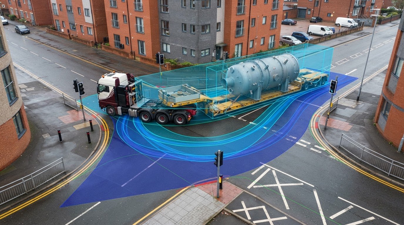
    Will the proposed entrance accommodate the actual abnormal-load vehicle, or only the dimensions assumed during early design? For projects involving oversized indivisible loads, that distinction can determine whether a manoeuvre is feasible. Swept path analysis for abnormal load vehicles models movement through a defined route segment or site layout, showing the space the vehicle’s wheels and body may occupy as it turns.

    A drawing can give a clear answer to a specific design question, but only when the vehicle details, manoeuvre and layout are accurate. A swept path envelope can reveal pinch points and potential conflicts. It cannot show conditions that are outside the model or the supplied information.

    This guide explains what the envelope represents, which project information supports a useful assessment, and how to interpret findings when considering access and design changes. ML Traffic Engineers UK provides project-specific Swept Path Analysis, with hands-on technical input from senior staff who each have over 35 years of traffic engineering experience. Projects across Greater London, South-East England, the West Midlands and North-West England can use a vehicle model matched to the proposed movement to inform access decisions.

    Key Takeaways

    • Swept path analysis for abnormal load vehicles tests whether specific manoeuvres fit the geometry shown in a project layout.
    • Off-tracking means front- and rear-wheel paths can differ as a vehicle turns, while the body or load may swing outwards.
    • Compare each relevant manoeuvre, such as turning at an entrance or navigating a junction, against the constraints it tests.
    • Provide the vehicle configuration, load dimensions and current access or site layout to give the assessment a clear basis.
    • Project-specific Swept Path Analysis can inform access feasibility and design decisions when its assumptions match the movement being considered.

    What swept path analysis for abnormal load vehicles can, and cannot, show

    Swept path analysis models the space a specified vehicle occupies while completing a defined manoeuvre. The modelled path is compared with the access or site layout to assess whether the vehicle can negotiate the geometry shown. For an abnormal-load vehicle, this can reveal tight turns, restricted turning areas and potential pinch points before design decisions are made.

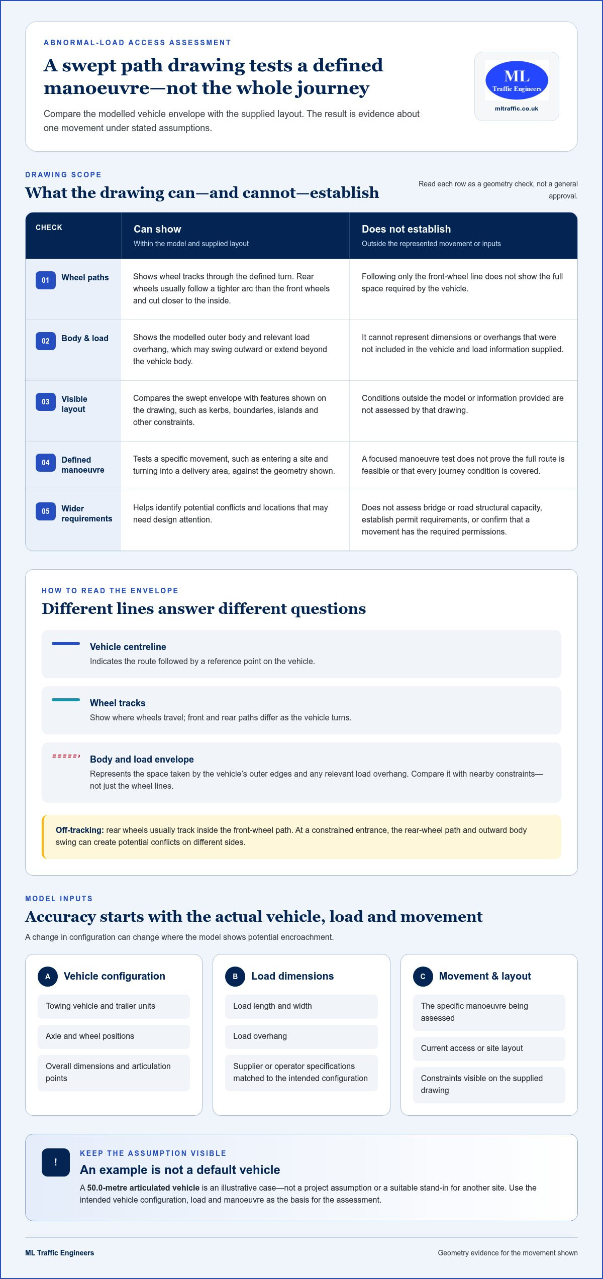
    The result is evidence about a particular movement under stated assumptions. It does not prove that every journey condition has been accounted for, that the full route is feasible, or that the movement has the required permissions. Treat the drawing as a focused test of geometry, not as a complete transport or approval assessment.

    What makes abnormal-load vehicle movements different?

    Vehicle length, width, articulation and load overhang all affect the space needed to turn. A long combination may need extra room for its front to swing out, while its rear wheels track inside the front-wheel path. An overhanging load may extend beyond the vehicle body and create a separate clearance concern.

    The model should distinguish the towing vehicle, trailer and load wherever their dimensions affect the envelope. No single set of dimensions represents every abnormal-load movement. A 50.0-metre articulated vehicle, for example, is an illustrative case, not a default project vehicle or a suitable assumption for another site. Use the intended configuration and manoeuvre as the basis for the assessment.

    What does a swept path drawing establish?

    A drawing shows the modelled vehicle path and swept envelope against the supplied layout. Depending on how the vehicle is represented, it can show how wheels track through a turn and how far the body or load extends around it. This helps identify potential conflicts with kerbs, boundaries, islands or other features visible on the drawing.

    The comparison supports a practical access decision: does the modelled movement appear to fit the available geometry, or does it highlight a location that needs design attention? Software such as AutoTrack software for swept path analysis can model vehicle movements, but the output still depends on accurate inputs and assumptions. ML Traffic Engineers UK also explains the role of AutoTURN swept path analysis in project assessments.

    Keep the drawing’s limits in view. It does not assess whether a bridge or road has the structural capacity for the vehicle, establish permit requirements, or confirm that every part of a route is workable. It addresses the manoeuvre represented on the drawing. The vehicle model, load configuration, layout and movement assumptions should therefore match the project decision the assessment is intended to inform.

    How abnormal-load swept path analysis models vehicle movement

    The assessment places a digital vehicle model on the project drawing and simulates a defined manoeuvre, such as entering a site and turning into a delivery area. The modelled path is compared with the available space. This helps show whether the vehicle’s wheels, body and load remain within the intended manoeuvring area or appear to cross a kerb, boundary or other constraint.

    The result depends on more than the vehicle’s overall length. Steering geometry affects how tightly the front wheels can turn, while articulation between a tractor and trailer changes how the units follow each other. Load overhang can extend beyond the trailer, creating a wider or longer envelope than the vehicle alone suggests. A difference in configuration can change where the model shows potential encroachment.

    Which vehicle and load details shape the model?

    How to read the swept path envelope

    Check what each line on the drawing represents. A vehicle centreline indicates the route followed by a reference point, while wheel tracks show where the wheels travel. The body and load envelope represents the space occupied by the vehicle’s outer edges and any relevant overhang. These lines answer different questions: the wheels may clear an obstruction even when the body or load passes close to it.

    Off-tracking is the difference between the paths of the front and rear wheels during a turn. As the front wheels steer around a corner, the rear wheels usually follow a tighter arc and cut closer to the inside. The vehicle’s outer body may also swing outward. At a constrained entrance, this can create potential conflicts on both sides. Inspect the full envelope rather than following only the front-wheel line.

    Simple plan-view schematic, not to scale:

    Site boundary: ┌────────────────────

    Vehicle path: Entry → front-wheel arc around corner

    Rear-wheel track: Tighter inside arc

    Body and load envelope: Outer swept area to compare with the boundary

    Use the drawing as a comparison, not a standalone guarantee. Its reliability depends on accurate vehicle details, site geometry and clearly stated manoeuvre assumptions. Before using it to inform a design decision, check that it represents the relevant layout and turning movement. For project-specific input on manoeuvrability and site access, ML Traffic Engineers UK’s Swept Path Analysis assesses the movement against the supplied design.

    Compare manoeuvres and constraints before accepting an abnormal-load layout

    A layout that works for a straight approach may still fail at the turn into a site. Review the manoeuvres that matter to the proposed movement instead of relying on a single path through the drawing. For each one, link the modelled envelope to a design question: is the entrance wide enough, can the vehicle align in the turning area, or could the trailer or load encroach on a feature shown on the plan?

    The table links common manoeuvres to the geometry they test. Include the movements relevant to the project.

    Manoeuvre Geometry or constraint tested Design question
    Straight access Entrance width, gates, walls and approach alignment Can the vehicle enter without its body or load conflicting with the edges shown?
    Turn into a site Corner radius, kerbs, islands and available turning area Can the vehicle complete the turn without the envelope crossing a constrained feature?
    Junction movement Road width, corner geometry and the position of adjacent boundaries Does the selected turn fit within the layout being assessed?
    Roundabout movement Entry, circulating space and exit geometry Can the vehicle follow the intended route through the roundabout shown?

    Which constraints should the drawing make visible?

    Review the features shown on the supplied layout, including kerbs, site boundaries, islands, gates and nearby structures. Compare each with the full vehicle, wheel and load envelope. If the model overlaps a kerb, that is a geometric conflict to address in the design. It does not establish whether the feature can withstand vehicle loading or whether an operational workaround is appropriate. Those are separate questions requiring their own assessment.

    Also distinguish plan-view clearance from overhead clearance. A swept path drawing can show where a vehicle travels across the mapped layout, but it does not establish clearance beneath a canopy, sign or other overhead feature unless suitable information is used to assess it. A clear path on the plan is not evidence of structural capacity either.

    When does a site manoeuvre differ from a whole-route question?

    Site-access swept path analysis tests specified movements against a defined area on the drawing, such as an entrance and internal turning space. A journey may encounter constraints beyond that boundary, including other junctions, structures or route restrictions. A site-access drawing therefore does not prove that the full route is feasible or provide route permission.

    Use each identified conflict to frame the next project decision: should the layout change, should another manoeuvre be assessed, or does the issue need a separate technical or operational review? This keeps swept path analysis for abnormal load vehicles focused on evidence the drawing can support. For project-specific analysis of vehicle manoeuvrability and site access, ML Traffic Engineers UK provides Swept Path Analysis.
    Swept Path Analysis for Abnormal Loads: UK Project Guide

    Prepare a reliable abnormal-load swept path assessment

    Start with a clear project question: which vehicle movement needs testing, and against which layout? Define the access point or route segment, then identify the manoeuvres that affect the design. Keep the scope specific. A drawing of a site entrance, for example, will not answer whether a separate junction elsewhere on the journey is workable.

    Set the assessment scope and assemble project information

    Bring together the intended vehicle and load configuration, the current site or access layout, and a description of the movement to test. Record which information has been supplied and which details have been verified against the project. This helps reviewers understand the model’s basis and identify assumptions that could affect the result.

    1. Define the movement. Identify the access point or route segment, direction of travel, entry or exit, and each relevant turn or manoeuvre.
    2. Specify the vehicle. Provide the towing vehicle and trailer arrangement, dimensions, articulation details and other configuration information that affects movement.
    3. Describe the load. Include its dimensions and any overhang beyond the vehicle or trailer. Identify which details are confirmed for the planned transport configuration.
    4. Supply the layout. Use the current drawing for the area being assessed, with relevant kerbs, boundaries, gates, islands and other constraints visible.
    5. Record assumptions. State the turning sequence, direction and any constraints included in the model. Separate assumptions from supplied or verified project information.
    6. Review the output. Compare the modelled envelope with the layout and note potential conflicts, drawing limitations and design questions that need attention.

    This process ties swept path analysis for abnormal load vehicles to a defined movement and traceable project inputs. If the vehicle configuration changes or the access layout is revised, the previous drawing may no longer represent the design under consideration. Keep the assessment with the relevant layout and assumptions so the project team can review them together.

    Review findings and communicate design implications

    Check that the drawing clearly identifies the vehicle, movement and layout, and explains the relevant assumptions. For each apparent pinch point, describe its location and the feature involved, then frame the design question: does the entrance geometry need reconsideration, or should another manoeuvre be tested? This presents the evidence without implying that the drawing resolves separate engineering or operational matters.

    For a practical explanation of the modelling approach, see the practical AutoTURN swept path guide. To apply project-specific vehicle details and access layouts, explore ML Traffic Engineers’ Swept Path Analysis, supported by hands-on technical input from senior staff with over 35 years of traffic engineering experience.

    How ML Traffic Engineers supports abnormal-load swept path projects

    For an abnormal-load project, the practical question is whether the specified vehicle can complete the required manoeuvre within the proposed access layout. ML Traffic Engineers provides Swept Path Analysis to examine vehicle manoeuvrability and access feasibility against project drawings. The assessment is tailored to the vehicle, load, layout and movement under consideration, helping project teams understand what the modelled geometry shows before making a design decision.

    A drawing is useful only when its assumptions reflect the intended movement. The analysis connects the vehicle configuration and load dimensions with the relevant entrance, turning area or other site constraint. Findings can identify where the layout may need further consideration, with conclusions kept specific to the information and manoeuvres assessed.

    Apply the analysis to the project’s planning context

    ML Traffic Engineers takes a hands-on approach to each project and considers variations in local planning context. An access arrangement needs to be understood within its site design and local authority context. Every senior staff member has over 35 years of traffic engineering experience, bringing technical perspective to the assessment and its interpretation.

    The drawing can inform discussion of access geometry, but its conclusions remain specific to the supplied vehicle, layout and manoeuvre. Swept Path Analysis does not guarantee planning approval or establish route permission. It gives project teams a focused way to examine manoeuvrability and consider whether the proposed layout accommodates the movement being assessed.

    ML Traffic Engineers supports projects across Greater London, Manchester, Birmingham, the West Midlands, Liverpool, Surrey, East Sussex, West Sussex, Hampshire, Berkshire and Buckinghamshire. This regional coverage enables the assessment to be considered in the context of the project location and its local planning circumstances.

    Take the next step with a project-specific discussion

    Before discussing an assessment, bring together the project location, intended vehicle and trailer configuration, load dimensions, current access layout and manoeuvre to examine. If some details are still assumptions, identify them clearly. This gives the discussion a practical starting point and focuses it on the access question the project needs answered.

    For a tailored assessment of vehicle movement and site-access feasibility, discuss your swept path analysis requirements with ML Traffic Engineers. Share the relevant project information to focus the assessment on the proposed manoeuvre and supplied layout.

    Turn access questions into a clear project decision

    Connect the movement you need to assess with the information that will make the drawing useful: the intended vehicle and load, the relevant access layout, and the manoeuvre under consideration. This gives the project team a clear basis for discussing what the model can demonstrate and where further design attention may be needed. Swept path analysis for abnormal load vehicles is most useful when its assumptions reflect the movement the project is planning.

    ML Traffic Engineers brings a hands-on approach to each assessment, with attention to local planning context. Every senior staff member has over 35 years of traffic engineering experience. That experience supports considered technical input, while keeping findings tied to the supplied project details rather than implying a particular approval or route outcome.

    Have an access question to resolve? Discuss your swept path analysis requirements with ML Traffic Engineers and take a considered next step for your project.

    Frequently Asked Questions

    Can swept path analysis guarantee that an abnormal-load vehicle can complete its journey?

    No. The assessment applies to the vehicle, layout and manoeuvres represented in the model, so it cannot guarantee passage through every journey condition. Temporary obstructions or a changed delivery configuration, for example, may differ from the drawing’s assumptions. Use the result to inform the specific design decision it tests, and treat wider route feasibility and permission as separate matters.

    Does a swept path analysis assess bridge strength or road loading capacity?

    No. Swept path analysis examines vehicle movement, not whether a bridge, road or other structure can carry the vehicle’s load. A model showing a vehicle passing over a bridge on plan is not evidence of structural capacity. Keep that question separate and use the relevant project documentation and technical assessment for the structure, often supported by civil and structural calculation platforms like EngiMetric. The swept path drawing should state its scope clearly, without implying a structural conclusion.

    Can one swept path drawing be used for different abnormal-load vehicles?

    Only if the drawing’s vehicle model and manoeuvre assumptions represent each vehicle being considered. Two combinations carrying the same load, for example, may have different trailer arrangements or steering characteristics. Compare the specifications, not just the overall length. If a vehicle’s dimensions, articulation or overhang differ, assess whether the existing model still represents it before using the drawing to inform access arrangements.

    Does swept path analysis include overhead clearance?

    Not automatically. A plan-view drawing shows horizontal movement, so it cannot establish clearance beneath a canopy, sign or bridge simply because the vehicle envelope fits on the plan. Height assessment requires suitable vertical information and a scope that addresses clearance. If overhead features could affect the movement, identify them separately and make sure the project review considers relevant heights rather than inferring clearance from a horizontal tracking result.

    Can a swept path assessment model a vehicle reversing?

    Yes, if reversing is defined as a movement and the model reflects the intended vehicle configuration and sequence. A site may require a vehicle to reverse from an entrance into a turning area, for example, which differs from entering forwards and turning. The drawing should make the direction and stages clear. Do not assume a forward movement demonstrates reverse access too; specify each movement the design needs to examine.

    Is swept path analysis the same as an abnormal-load permit?

    No. Swept path analysis assesses a specified vehicle movement; the drawing does not grant route permission. Keep these workstreams distinct in project records. Requirements and planning context can vary by location, including across Greater London, Manchester, Birmingham, the West Midlands, Liverpool, Surrey, East Sussex, West Sussex, Hampshire, Berkshire and Buckinghamshire. Consult the relevant UK authority for current requirements before making regulatory decisions.

    Can swept path analysis identify a problem at a roundabout?

    Yes, if the roundabout and intended vehicle movement are included in the model. An assessment might examine whether the vehicle’s envelope conflicts with an island during a specified turn, for example. Be precise about which entry, circulating movement or exit the drawing covers. Swept path analysis for abnormal load vehicles can help identify a geometric issue at that location, but it does not assess every approach or onward route condition.

    Michael Lee

    Article by

    Michael Lee

    Transport planner with over 35 years' experience.

    Disclaimer

    The content on mltraffic.co.uk, including all technical articles, guides, and resources, is provided for general informational and educational purposes only. It is not intended to constitute professional advice in traffic engineering, transportation planning, development approvals, or any other technical or legal field.
    While ML Traffic Engineers makes every reasonable effort to ensure the accuracy, completeness, and timeliness of the information published, we do not provide any warranties or representations (express or implied) regarding its reliability, suitability, or availability for any particular purpose. Any reliance you place on the content is strictly at your own risk.
    In no event shall ML Traffic Engineers, its directors, employees, authors, or affiliates be liable for any direct, indirect, incidental, special, consequential, or punitive damages (including, without limitation, loss of profits, data, or business opportunities) arising out of or in connection with the use of, or inability to use, any information provided on this website.
    The articles and guides on this site are not a substitute for engaging a qualified, professional traffic engineer to assess your specific project requirements. For tailored advice, compliance assessments, or traffic engineering services, please contact a competent professional.
    This disclaimer may be updated from time to time without notice. By accessing or using this website, you agree to be bound by the most current version of this disclaimer.
  • 2026 Wind Turbine Delivery: Swept Path Analysis Guide

    2026 Wind Turbine Delivery: Swept Path Analysis Guide

    A single 80-metre turbine blade manoeuvring through a tight rural junction in the UK isn’t just a logistical challenge; it’s a high-stakes operation where a five-centimetre miscalculation can derail a multi-million pound project. You understand that the bridge between a theoretical route and a viable 2026 deployment is built on technical precision. Utilizing specialist swept path analysis for wind turbine delivery is the only way to transform these logistical risks into verified certainties. The fear of costly mid-construction showstoppers or planning application delays due to transport objections is a reality for many developers managing the complexities of Abnormal Indivisible Loads (AILs).

    By implementing precision modelling, you can proactively mitigate these risks and secure planning permission with zero transport-related conditions. This guide explores how specialist software provides the technical authority needed to satisfy local highway authorities and overcome statutory hurdles. You’ll discover how clear, actionable route access reports verify project feasibility from the outset, providing your hauliers with the confidence to execute deliveries safely. We’ll outline the essential steps to turn complex logistical hurdles into a streamlined, approved transport strategy that protects both your timeline and your budget.

    Key Takeaways

    • Master the technical requirements for modelling Abnormal Indivisible Loads (AILs) using specialised vehicle templates for extendable trailers and blade lifters.
    • Discover how precision swept path analysis for wind turbine delivery provides the verified evidence needed to secure planning approval and satisfy Local Highway Authorities.
    • Identify critical failure points, such as blade tip sweep on rural UK routes, and learn how to plan effective temporary mitigation works.
    • Reduce project risk by moving beyond automated software outputs to expert, safety-conscious route access assessments that account for real-world constraints.
    • Gain the haulier confidence required for successful 2026 project execution by eliminating transport-related planning conditions through professional engineering reports.

    The Role of Swept Path Analysis in Wind Turbine Logistics

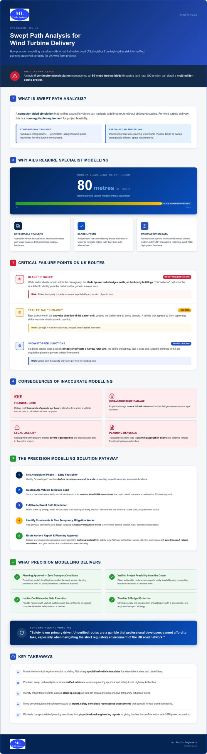
    Swept path analysis is a computer-aided simulation used to verify that a specific vehicle can navigate a defined route without striking obstacles. In the context of large-scale renewable energy infrastructure, this technical exercise is a non-negotiable requirement for project feasibility. Wind turbine components qualify as Abnormal Indivisible Loads (AILs) under UK law because they cannot be transported in smaller sections without significant structural compromise. Modern wind turbine components and dimensions, with some blades now reaching 80 metres or more, demand a level of precision that standard HGV tracking simply cannot provide.

    Traditional heavy goods vehicles follow predictable paths based on fixed axle configurations. In contrast, specialized swept path analysis for wind turbine delivery must account for trailers with independent rear-axle steering and extendable chassis. These vehicles possess unique steering characteristics that dramatically alter the space required at junctions. Precision modelling ensures that these complex movements are documented and verified long before a single component arrives at a UK port.

    Why Feasibility Hinges on Precision

    Identifying “showstopper” junctions early in the site acquisition phase prevents wasted investment in unviable locations. If a blade cannot clear a specific bridge or navigate a narrow rural lane, the entire project may face a dead end. ML Traffic Engineers UK integrates SPA into broader Transport Assessments to ensure every junction is scrutinized before developers commit to a site. This level of technical authority reduces the risk of planning refusals and ensures the local highway authority remains satisfied with the proposed delivery strategy from the outset.

    The Consequences of Inaccurate Modeling

    Errors in the planning stage lead to catastrophic failures during the delivery phase. If a vehicle cannot pass a point that was previously deemed safe on paper, the resulting delays cost thousands of pounds per hour in standing time. Beyond financial loss, inaccurate modelling poses a physical threat to rural infrastructure. Striking a third-party property or damaging a historic bridge creates severe legal liabilities and erodes public trust in the project. Safety is our primary driver. Unverified routes are a gamble that professional developers cannot afford to take, especially when navigating the strict regulatory environment of the UK road network.

    Modeling Abnormal Indivisible Loads (AILs): Technical Requirements

    Modeling Abnormal Indivisible Loads (AILs) requires moving beyond standard vehicle profiles. We utilize specialized templates for extendable trailers, tower adapters, and blade lifters to reflect the physical reality of modern haulage. This technical precision is vital because wind turbine components don’t follow standard HGV tracking patterns. Professional swept path analysis for wind turbine delivery must account for the unique steering geometry of these vehicles, particularly independent rear-axle steering which allows the trailer to “crab” or navigate tighter radii than a fixed-axle alternative.

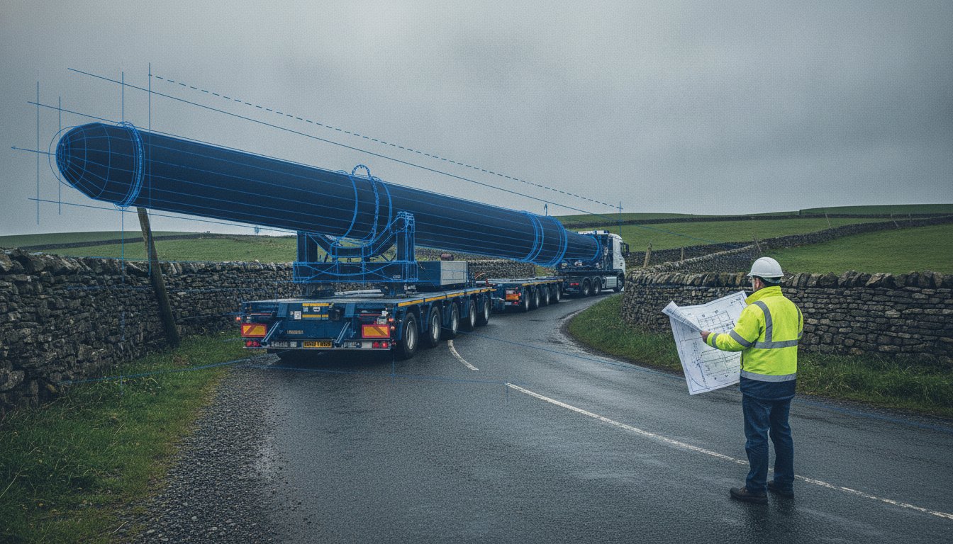
    The “Blade Tip” maneuverability is the most frequent point of failure on narrow UK roads. While the trailer wheels might remain within the carriageway, the blade tip often over-sails hedges, walls, or third-party buildings. We simulate this “airborne” path to identify potential collisions that generic surveys miss. We also model the “kick-out” of the trailer tail. This occurs when the rear axles steer in the opposite direction of the tractor unit, causing the trailer’s rear to swing outward. Without accounting for this swing, a vehicle that appears to fit on paper may strike roadside infrastructure in practice.

    Customizing Vehicle Templates for 2026 Turbine Models

    Modern blades often exceed 80 metres in length, making generic vehicle models insufficient. We source manufacturer-specific technical data to build custom AutoTURN simulations that match the exact hardware scheduled for your 2026 deployment. This level of detail is a prerequisite for successful wind energy development and infrastructure planning. For extreme terrain or narrow village corridors, we simulate blade lifters. These specialized trailers can tilt the blade up to 60 degrees, allowing the load to pass over obstacles rather than through them.

    The 3D Element: Vertical Swept Path Analysis

    Ground clearance is as critical as lateral space. Low-slung trailers frequently “ground out” on hump-backed bridges or steep gradients common in regions like Cornwall. Vertical swept path analysis assesses the trailer’s underside against the road’s longitudinal profile to prevent these showstoppers. We also model the vertical height of the load to ensure clearance under overhanging utility lines and trees. If your project requires this level of technical verification, our specialists can provide comprehensive swept path analysis to secure your delivery route. This proactive approach ensures the trailer does not ground out or strike overhead obstacles during transit.

    Overcoming Planning Hurdles with Route Access Assessments

    Securing planning permission for renewable energy projects in England requires more than just a proposed route. It demands rigorous technical evidence that satisfies both National Highways and Local Highway Authorities (LHAs). In this regulatory environment, swept path analysis for wind turbine delivery serves as the primary evidence within your Transport Statement or Assessment. It moves the conversation from speculative theory to verified engineering, proving that Abnormal Indivisible Loads (AILs) won’t compromise road safety or infrastructure integrity.

    Statutory consultees often raise concerns regarding the cumulative impact of multiple wind farm deliveries on a single strategic route. If several projects are scheduled for 2026, planners need assurance that the road network can handle the combined volume without structural degradation. When the analysis identifies a need for physical route modifications, we facilitate the technical approval process for S278 and S38 agreements. This ensures that any temporary or permanent highway works meet the strict standards required by UK law.

    Navigating Local Highway Authority (LHA) Objections

    LHAs typically demand a minimum safety clearance margin, often 0.5 metres, between the vehicle’s swept path and fixed roadside obstacles. Meeting this requirement is essential to avoid automatic objections. We provide multi-layered CAD drawings that offer visual proof of these clearances at every critical junction. These drawings illustrate the exact relationship between the load and the existing environment, which is vital for addressing public safety concerns and defining traffic management strategies during the delivery window.

    The Route Access Report (RAR)

    A professional Route Access Report (RAR) is the document that makes your project planning ready. It synthesises the findings of the swept path analysis into a clear, actionable strategy for the planning committee. A robust RAR must include detailed junction assessments, identified constraints, and proposed mitigation measures. This report forms the technical bridge to your Construction Traffic Management Plan (CTMP). At ML Traffic Engineers UK, we focus on producing reassuring, professional reports that build trust with planning officers, helping you eliminate transport-related planning conditions and move toward a successful project launch.

    Identifying Physical Constraints and Temporary Mitigation Works

    Accurate swept path analysis for wind turbine delivery depends entirely on the quality of the base map. We utilize detailed topographic surveys to ensure every kerb line, telegraph pole, and building frontage is accounted for within the digital model. This high-resolution data allows us to distinguish between minor obstacles and project-ending constraints. While a generic map might suggest a route is clear, our precision modeling often reveals hidden conflicts that require immediate attention before a planning application is submitted. We focus on identifying these bottlenecks early to prevent costly delays during the construction phase.

    Common Logistical Constraints in the UK

    Street furniture such as bollards, directional signs, and traffic islands are the most frequent hurdles encountered on the UK road network. While these are often seen as minor inconveniences, they require formal removal and reinstatement plans that must be agreed upon with the local authority. Third-party land is another critical factor. Identifying where a blade tip over-sails a private boundary is essential for securing legal access or “over-sail” rights. We also assess structural constraints, checking the load-bearing capacities of culverts and bridges along the route. Ensuring the chosen path can support the extreme gross vehicle weight of an AIL is a fundamental safety requirement that we verify through our technical reporting.

    Designing Effective Mitigation Solutions

    Once constraints are identified, we design targeted mitigation strategies to ensure safe passage. Temporary widening of junctions using heavy-duty trackway or gravel can provide the necessary clearance without requiring permanent alterations to the highway. This distinction is vital for planning, as temporary works are often viewed more favourably by local communities and councils. Alternatively, employing blade lifter technology allows the load to navigate tight radii by tilting the component over existing obstacles like hedges or walls. This technology reduces the need for intrusive ground works and simplifies the regulatory approval process. We also coordinate with utility companies to manage overhead line height adjustments, ensuring tower sections don’t strike low-hanging cables.

    Common mitigation measures include temporary surfacing, street furniture removal, and vegetation management.

    If you need to identify potential bottlenecks and secure your 2026 delivery route, book a specialist swept path analysis to safeguard your project’s feasibility and timeline.

    2026 Wind Turbine Delivery: Swept Path Analysis Guide

    Why Professional Traffic Engineering is Critical for Wind Farm Success

    Professional traffic engineering bridges the gap between digital simulation and operational reality. While software provides the framework, the true value lies in the expert interpretation of those outputs. A computer program identifies a collision, but an engineer determines the most viable mitigation strategy to keep the project moving. By choosing a specialist approach to swept path analysis for wind turbine delivery, you ensure that every manoeuvre is scrutinized by a professional who understands the high-stakes nature of UK renewable energy infrastructure. Technical authority is essential when defending a route access report before a planning committee or during a public inquiry. We integrate these technical findings into a comprehensive transport planning strategy that protects your project’s timeline and reputation.

    Reducing Logistical Uncertainty

    We provide hauliers with a digital dry run of the delivery route, simulating the exact vehicle and load dimensions scheduled for 2026. This process identifies potential conflicts before they manifest on-site, allowing for the optimization of the route to minimize community disruption and cost. Our active voice capability means ML Traffic Engineers UK manages the entire process, from the initial survey to final approval. This comprehensive oversight eliminates communication gaps and ensures that the technical requirements discussed in previous sections are translated into actionable field plans. We take pride in our precision, ensuring that “near enough” never puts your project at risk.

    Partnering with ML Traffic Engineers UK

    Founded in 2014, ML Traffic Engineers UK acts as the guardian of project feasibility. We specialize in AutoTURN simulations and maintain a deep understanding of the intricate regional regulations within the UK planning system. Our reports carry the technical authority required to withstand rigorous scrutiny from statutory consultees. This professional integrity is a cornerstone of our service, offering you peace of mind in a strictly regulated environment. We view our role as a vital partner in your project’s success, ensuring public and worker safety through adherence to industry benchmarks. Beyond logistical planning, developers often seek expert guidance from providers like The Energy Desk on business energy procurement UK to manage the operational costs of their renewable energy assets. If you’re ready to secure your transport strategy, we recommend starting with a site feasibility review to identify any immediate logistical risks.

    Securing Your 2026 Delivery Route

    Securing planning approval for renewable energy infrastructure requires technical precision that leaves no room for ambiguity. By utilizing specialist swept path analysis for wind turbine delivery, you transform complex logistical challenges into a verified, manageable strategy. You’ve seen how expert interpretation of AutoTURN simulations identifies physical constraints early, allowing for targeted mitigation that satisfies Local Highway Authorities. This proactive approach eliminates the risk of costly delays and ensures your project remains compliant with UK regulatory standards.

    ML Traffic Engineers UK provides the technical authority needed to navigate the high-stakes environment of AIL transport. Our specialist AutoTURN operators deliver comprehensive Route Access Reporting backed by a proven track record with UK Local Highway Authorities. We manage the full project lifecycle to ensure your site remains feasible from inception to completion. Take the next step in safeguarding your project’s timeline and budget.

    Request a Swept Path Analysis Quote for Your Wind Project and ensure your 2026 delivery schedule is built on a foundation of engineering certainty.

    Frequently Asked Questions

    What is the maximum length of a wind turbine blade for standard UK road delivery?

    Modern wind turbine blades frequently exceed 80 metres in length for 2026 deployments. Under UK law, any load exceeding 18.65 metres is classified as an Abnormal Indivisible Load (AIL). These components require specialized extendable trailers and often need police or private escorts. Precise modeling is vital because these dimensions push the physical limits of the UK’s rural road network, particularly in regions like Cornwall where narrow lanes are common.

    Do I need a topographic survey before conducting swept path analysis?

    A topographic survey is essential for providing the accurate base map required for technical modeling. While OS data might suffice for standard cars, it lacks the precision needed to verify 80-metre blade clearances. A topographic survey captures exact kerb positions, telegraph poles, and building frontages. This high-resolution data ensures our swept path analysis for wind turbine delivery is grounded in physical reality rather than theoretical estimates.

    How does swept path analysis account for the “over-sail” of turbine blades?

    We model the blade as a separate 3D entity within the simulation rather than just a vehicle chassis. This allows the software to track the airborne path of the load as it swings over third-party land or roadside vegetation. Identifying these over-sail areas is critical for securing legal access agreements. Our reports clearly distinguish between the wheel path and the load path to ensure complete transparency for highway authorities.

    What is the typical safety margin required by UK highway authorities for AILs?

    Local Highway Authorities in England typically demand a minimum safety clearance of 0.5 metres from any fixed obstacle. In more restricted or sensitive environments, authorities might request a larger margin to account for driver error or uneven road surfaces. Our technical drawings explicitly highlight these clearance zones. Providing this visual proof helps reduce the risk of planning objections and demonstrates a commitment to public and worker safety.

    Can swept path analysis be used to justify temporary road widening on third-party land?

    Yes, SPA serves as the primary technical justification for any required highway modifications. If the analysis proves a load cannot navigate a junction without striking a boundary, the report provides the evidence needed to negotiate temporary widening or street furniture removal. This documentation is vital for S278 agreements. It allows developers to prove that the proposed works are a functional necessity for the project’s successful delivery.

    How long does it take to complete a route access assessment for a wind farm?

    A comprehensive route access assessment for a wind farm typically takes between two and four weeks to complete. This timeline accounts for initial site surveys, custom vehicle template creation, and rigorous junction modeling. Complex routes with multiple showstopper points may require additional time for technical interpretation and mitigation design. We prioritize efficiency and accuracy to ensure your planning submission remains on schedule for 2026 project deadlines.

    Is swept path analysis required for both the delivery and the return of empty trailers?

    Yes, we recommend modeling both the delivery of the components and the return journey of the empty trailers. While empty trailers are shorter, they often utilize different rear-steering configurations or follow alternative return routes to avoid congestion. Ensuring the return journey is also verified prevents unforeseen logistical issues. This comprehensive approach provides hauliers with total confidence and satisfies the requirements of a robust Construction Traffic Management Plan.

    What software does ML Traffic Engineers use for turbine delivery simulations?

    ML Traffic Engineers utilizes industry-standard AutoTURN software for all technical simulations. This software allows us to build manufacturer-specific vehicle templates that reflect the exact steering geometry of modern turbine haulage equipment. By using AutoTURN, we provide the technical authority required by National Highways and local councils. This ensures that every swept path analysis for wind turbine delivery we produce meets the strict regulatory standards of the UK planning system.

    Michael Lee

    Article by

    Michael Lee

    Transport planner with over 35 years' experience.

    Disclaimer

    The content on mltraffic.co.uk, including all technical articles, guides, and resources, is provided for general informational and educational purposes only. It is not intended to constitute professional advice in traffic engineering, transportation planning, development approvals, or any other technical or legal field.
    While ML Traffic Engineers makes every reasonable effort to ensure the accuracy, completeness, and timeliness of the information published, we do not provide any warranties or representations (express or implied) regarding its reliability, suitability, or availability for any particular purpose. Any reliance you place on the content is strictly at your own risk.
    In no event shall ML Traffic Engineers, its directors, employees, authors, or affiliates be liable for any direct, indirect, incidental, special, consequential, or punitive damages (including, without limitation, loss of profits, data, or business opportunities) arising out of or in connection with the use of, or inability to use, any information provided on this website.
    The articles and guides on this site are not a substitute for engaging a qualified, professional traffic engineer to assess your specific project requirements. For tailored advice, compliance assessments, or traffic engineering services, please contact a competent professional.
    This disclaimer may be updated from time to time without notice. By accessing or using this website, you agree to be bound by the most current version of this disclaimer.