Tag: Visibility Splays

  • Junction Visibility Analysis: 2026 Developer’s Guide

    Junction Visibility Analysis: 2026 Developer’s Guide

    A restrictive site frontage doesn’t have to be the death knell for your development’s access potential. Many developers treat visibility splays as rigid, immovable obstacles that eat into valuable developable land, but the reality is far more flexible. If you’ve faced objections from Highway Officers or felt overwhelmed by the conflicting requirements of the DMRB and Manual for Streets, you know that securing a junction visibility analysis for planning applications is often the most contentious part of the process. You likely feel the pressure of balancing rigorous safety standards with your project’s commercial viability.

    This guide provides the technical clarity you need to master UK highway safety criteria and ensure your access design is planning-compliant. We’ll break down the 2026 regulatory landscape, including the latest updates to the consolidated Manual for Streets and the alphanumeric DMRB standards. You’ll learn how to use site-specific 85th percentile speed data to justify tighter splays, successfully validate your Transport Statement, and protect your project from costly delays. We move from initial speed assessments to final design execution, providing the precision required for a successful planning outcome.

    Key Takeaways

    • Identify whether your project requires Manual for Streets or DMRB standards to ensure your access design aligns with the correct road hierarchy and speed.
    • Understand how a professional junction visibility analysis for planning applications secures validation for your Transport Statement and mitigates safety objections.
    • Learn how to precisely calculate X and Y distances to minimize unnecessary land take while maintaining essential Stopping Sight Distance requirements.
    • Resolve land-take constraints by using site-specific 85th percentile speed surveys to justify visibility splays that work within your existing site boundaries.
    • Strengthen your planning submission by integrating visibility splays with Swept Path Analysis to create a robust and technically compliant access strategy.

    What is Junction Visibility Analysis in Transport Planning?

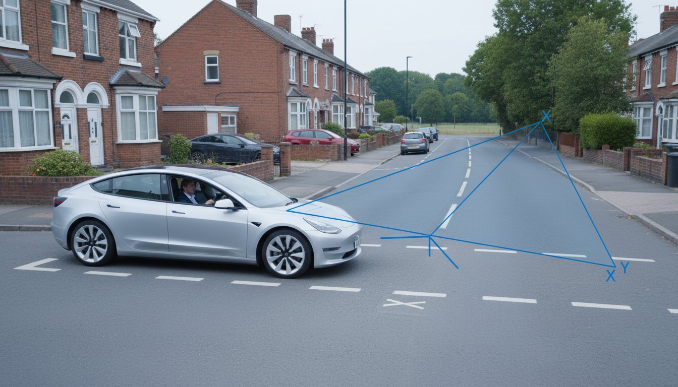
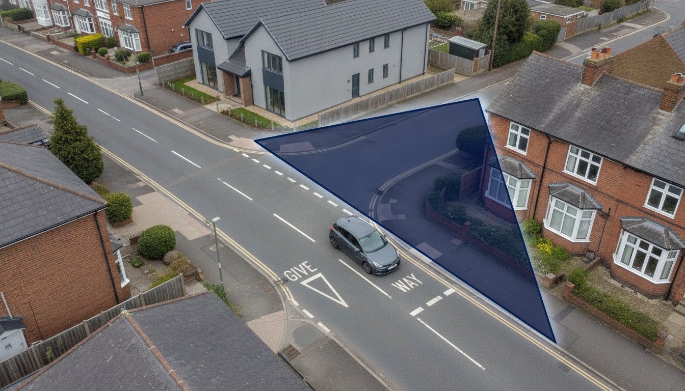
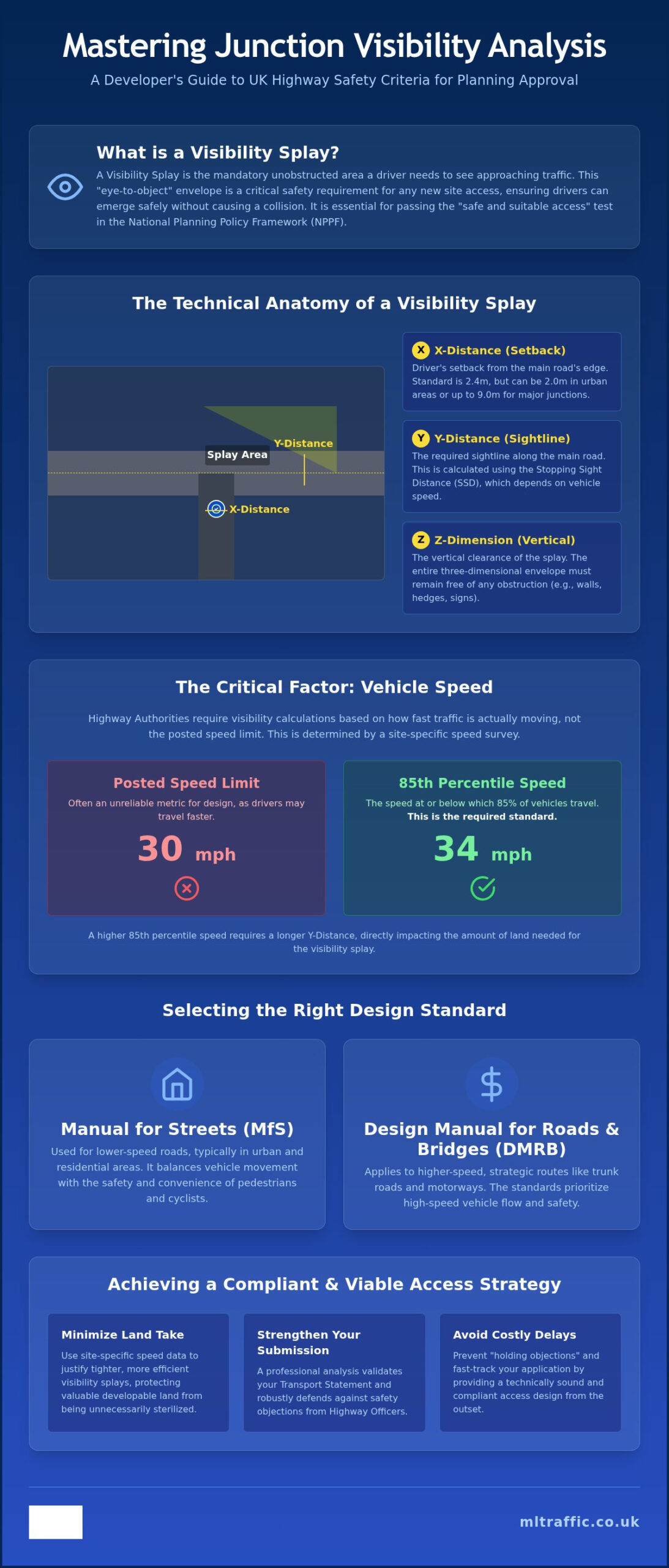
    A Visibility Splay is the unobstructed area a driver needs to see traffic. In the context of highway engineering and the Geometric design of roads, this analysis ensures that any new access point doesn’t compromise public safety. A junction visibility analysis for planning applications is a mandatory technical assessment used to prove that drivers emerging from a site can see, and be seen by, approaching vehicles in time to avoid a collision. It’s the “eye-to-object” envelope that defines whether a site access is safe or a potential hazard.

    Planning Officers and Highway Engineers prioritize this because safety is a non-negotiable statutory requirement. If a developer cannot demonstrate adequate visibility, the application fails the “safe and suitable access” test set out in the National Planning Policy Framework (NPPF). It isn’t just about looking left and right; it’s about the technical envelope required for safe interaction between all road users, including pedestrians and cyclists. Precision in these drawings is essential for securing a recommendation for approval.

    There’s a direct mathematical relationship between vehicle speed and the physical space required to stop. As speeds increase, the distance a vehicle travels during the driver’s perception-reaction time and the subsequent braking phase grows. This total distance forms the basis of the visibility splay’s “Y-distance.” Accurate data is the only way to satisfy a Highway Officer’s scrutiny, especially when site constraints are tight.

    The Consequences of Poor Visibility Design

    Designing an access with substandard visibility leads to immediate friction with the Local Highway Authority. This often results in a “holding objection,” which halts the planning process until you provide a compliant solution. Beyond the regulatory hurdle, poor design increases the real-world risk of “failure to look” accidents. These incidents occur when the physical layout prevents a driver from seeing a hazard in time to react. If your site has limited frontage, failing to address these visibility constraints early can compromise the entire project’s viability and safety rating.

    Visibility Splays vs. Stopping Sight Distances (SSD)

    Stopping Sight Distance (SSD) is the physical distance a vehicle travels from the moment a driver identifies a hazard to the moment the vehicle stops. This calculation is the technical foundation of every junction visibility analysis for planning applications. While junction visibility focuses on the “eye-to-object” envelope at an intersection, forward visibility refers to the sightlines required on bends or crests to ensure drivers can see stationary hazards ahead. Both are essential components of a robust Transport Statement. Using site-specific speed data ensures these distances are accurate, preventing the over-provision of visibility that wastes developable land.

    The Technical Anatomy of a Visibility Splay: X, Y, and Z Distances

    A visibility splay is a three-dimensional envelope that must remain clear of obstructions to ensure safe passage for all road users. The “X” distance represents the driver’s position, measured from the edge of the running carriageway back into the minor arm of the junction. While 2.4 meters is the standard setback for most residential developments, major junctions under DMRB guidelines may require 4.5 meters or even 9.0 meters. In constrained urban environments, a reduced 2.0 meter “X” distance is sometimes defensible. The “Y” distance extends from the junction along the main road, representing the sightline needed to see oncoming traffic. These two dimensions, paired with the vertical “Z” dimension, create the geometric footprint that Highway Officers scrutinize during a junction visibility analysis for planning applications.

    Calculating the Y-Distance Correctly

    The Y-distance is frequently the most contested element in a planning submission. It’s determined by the Stopping Sight Distance (SSD), which is the total distance a vehicle travels before coming to a complete stop. Instead of relying on the posted speed limit, Highway Authorities require the 85th percentile speed, the speed at or below which 85% of vehicles are observed to travel under free-flowing conditions. If a speed survey reveals traffic is moving faster than the limit, the required Y-distance will increase. You must also adjust these calculations for road gradients; downhill slopes significantly extend braking distances. Ongoing CIHT Visibility Research continues to refine how these distances are applied to balance driver safety with the needs of pedestrians and cyclists.

    Eye and Object Heights (The Z-Dimension)

    The “Z” dimension ensures that visibility isn’t just a flat line on a map but a functional clear zone. For car drivers, the standard eye height is between 1.05m and 2.0m above the road surface. However, if your development serves HGVs, the eye height increases to 2.0m, which can actually improve visibility over certain obstacles. The object height is equally vital; the splay must provide a clear view of objects as low as 0.6m, such as children or cyclists. To satisfy planning requirements, architects should provide section drawings that clearly show a hatched “clear zone” between these heights. This demonstrates that no walls, fences, or landscaping will block the critical line of sight. Ensuring these technical details are correct from the start helps in the successful validation of Transport Statements and avoids costly redesigns.

    MfS vs. DMRB: Selecting the Right Visibility Standards

    Selecting the correct technical standard is the most critical step in a junction visibility analysis for planning applications. The choice between Manual for Streets (MfS) and the Design Manual for Roads and Bridges (DMRB) dictates the scale of your visibility splays and, ultimately, the amount of developable land you retain. Using the wrong standard doesn’t just result in a request for more information; it often leads to an automatic planning refusal. This happens because Highway Officers view the misapplication of standards as a failure to recognize the functional nature of the road. While MfS supports urban and residential environments, DMRB is a rigorous framework intended for the strategic road network. Navigating the grey area at the 40mph threshold requires precise data rather than assumptions.

    When to Apply Manual for Streets (MfS)

    Manual for Streets (MfS) is the primary guidance for roads where measured speeds are 37mph (60kph) or lower. It shifts the design focus from “movement”, the rapid flow of vehicles, to “place”, which considers the needs of residents, pedestrians, and cyclists. The benefits of MfS are significant for developers. It permits shorter Y-distances and more flexible X-distances, such as the 2.0m setback often used in constrained urban settings. A new consolidated version of MfS is currently in final development, with a draft circulated in April 2026. This update reinforces the mandate to design safer, more accessible streets that don’t prioritize vehicle speed at the expense of site viability.

    Challenging DMRB Requirements

    Challenging a Highway Officer’s demand for DMRB standards is possible when you have the right evidence. Many authorities default to DMRB for any road with a 40mph limit, but this isn’t always appropriate for non-trunk roads that function as urban streets. Your secret weapon is the speed survey. By deploying Automatic Traffic Counters (ATC), you can prove the 85th percentile speed is actually below the 37mph threshold. This data allows you to apply MfS principles even on higher-speed roads, potentially saving meters of site frontage. When you combine this data-driven justification with Swept Path Analysis, you provide a comprehensive technical package that is difficult for authorities to ignore. This level of precision is exactly what’s needed to secure approval for complex access designs.

    Common Constraints: Third-Party Land, Topography, and Vegetation

    Securing a junction visibility analysis for planning applications often reveals physical or legal barriers that a simple site plan cannot resolve. One of the most significant hurdles is the “Blue Land” vs. “Red Land” dilemma. If your required visibility splay crosses land outside your ownership (Blue Land), the Highway Authority will likely object unless you can secure a legal agreement with the neighbor or prove the land is part of the public highway. For land already within the highway boundary, a Section 278 agreement is the standard mechanism to secure the right to clear obstructions and maintain sightlines in perpetuity.

    Physical obstructions like bridge abutments, telegraph poles, or existing buildings create permanent blind spots that geometric design cannot always bypass. Topography also plays a critical role. If the main road is significantly higher or lower than your site access, the vertical curve (crest or sag) might block the driver’s view even if the horizontal splay looks perfect on paper. Technical standards require the triangular visibility zone to remain clear of all obstructions between 0.6m and 2.0m above the road level to ensure inter-visibility between drivers and vulnerable road users. This three-dimensional clearance is a non-negotiable foundation of a safe access design.

    Managing Vegetation and Landscaping

    Vegetation is a dynamic constraint that requires a lifetime management plan. Planning conditions typically mandate that visibility splays remain clear of any growth exceeding 0.6m in height. This creates a conflict when protected trees or established hedgerows sit within the splay. In these cases, you might need to negotiate a specialized maintenance strategy or, if safety is compromised, consider a slight shift in the access location. Highway Officers won’t accept “seasonal maintenance” as a solution; the splay must be clear 365 days a year to meet safety criteria. If a protected tree is the issue, early engagement with an arboriculturist is necessary to balance ecological preservation with highway safety.

    Urban Constraints and “Zero Splay” Realities

    In dense environments, such as central London, providing a traditional visibility splay is often impossible due to the proximity of neighboring buildings. These “zero splay” scenarios require a bespoke approach to safety. While some developers suggest using mirrors or “Stop” signs to mitigate poor sightlines, most Councils strongly dislike these measures due to maintenance and liability issues. Instead, you must demonstrate that the low vehicle speeds and high pedestrian activity justify a deviation from standard splay dimensions. For projects in high-density areas, Understanding Transport Assessment London is essential to navigating these intricate regional regulations. If you’re facing land ownership constraints or technical objections, our team can provide the precise Transport Statements and visibility analysis needed to move your application forward.
    Junction Visibility Analysis: 2026 Developer’s Guide

    Integrating Visibility Analysis into Your Transport Statement

    A junction visibility analysis for planning applications is the technical anchor of any successful Transport Statement. It provides the empirical evidence required to satisfy the “Safe and Suitable Access” mandate within the National Planning Policy Framework (NPPF). Without this data, your application lacks the necessary proof that drivers can interact safely with the existing highway network. A professional analysis doesn’t just show a triangle on a map; it demonstrates a deep understanding of driver behavior and vehicle mechanics. Integrating this early in your project lifecycle prevents the need for reactive design changes that often shrink developable site areas.

    To provide a truly robust technical package, you must combine visibility splays with Swept Path Analysis. While visibility ensures a driver can see oncoming hazards, Swept Path Analysis proves that the vehicle can physically complete the turn without overrunning curbs or encroaching on opposing lanes. Highway Officers look for this synergy to confirm that the proposed access is functional in the real world. When these two assessments align, they create a compelling safety case that streamlines the negotiation process with Local Highway Authorities.

    The Data Collection Phase

    Reliable visibility splays start with high-quality data. Relying on the posted speed limit is a common mistake that leads to planning objections; Highway Officers know that actual vehicle speeds often differ from the signs. We use Automatic Traffic Counters (ATC) to collect 24/7 speed data over a full week. This provides a precise 85th percentile speed, which is the industry standard for determining Y-distances. Using accurate, site-specific data often allows us to justify shorter visibility splays than the default standards might suggest, potentially saving significant land at the site frontage.

    Securing Professional Support

    ML Traffic Engineers reduces the regulatory pressure on developers by providing precise engineering and expert negotiation. We handle the entire project lifecycle, from the initial traffic survey to the final technical report. This fully-managed approach ensures that your junction visibility analysis for planning applications is accurate, compliant, and ready for scrutiny. Our experts understand the intricate regional regulations across England, allowing you to focus on the broader development while we manage the highway safety criteria. You can Request a Transport Statement quote to secure the technical support needed for your submission.

    Before submitting your application, ensure your visibility drawings include the following elements:

    • Clear Scaling: Drawings should be at 1:500 or 1:200 for clarity.
    • Labeled Distances: Both X and Y distances must be clearly marked and measured from the correct points.
    • Data Citations: State whether the splay is based on MfS or DMRB and cite the speed survey source.
    • Vertical Clearance: Indicate that the zone between 0.6m and 2.0m will remain unobstructed.
    • Site Context: Include existing site boundaries and any permanent physical constraints.

    Securing Your Planning Approval with Technical Precision

    Mastering the technical requirements of visibility splays is the most effective way to protect your development from costly highway objections. By utilizing site-specific 85th percentile speed data, you can move away from restrictive speed limit assumptions and justify splay dimensions that maximize your site’s developable potential. Selecting the correct design standard, whether Manual for Streets or DMRB, ensures your access strategy aligns with UK safety criteria and specific regional expectations. Integrating a junction visibility analysis for planning applications with other technical assessments like Swept Path Analysis provides the comprehensive evidence Highway Officers require for validation.

    ML Traffic Engineers UK provides expert analysis for UK planning applications. We are specialists in Transport Statements and Assessments, providing reliable data collection including Speed and Parking Surveys to reduce your regulatory pressure. Our team manages the full project lifecycle to ensure your technical drawings and reports are planning-ready. Contact ML Traffic Engineers UK for a professional Visibility Analysis to ensure your project meets the highest safety standards. We are ready to help you navigate these intricate regulations and secure a safe, compliant access design for your next development.

    Frequently Asked Questions

    What is the minimum visibility splay for a 30mph road?

    The standard visibility splay for a road with a 30mph speed limit is typically 2.4 meters for the X-distance and 43 meters for the Y-distance under Manual for Streets (MfS) guidance. This Y-distance is based on the Stopping Sight Distance (SSD) for vehicles traveling at that speed. If a speed survey proves that the 85th percentile speed is lower than 30mph, we can often justify a reduced Y-distance to maximize your site’s frontage.

    Can a visibility splay cross over a neighbour’s driveway or garden?

    A visibility splay can physically cross third-party land, but it must be legally secured to remain unobstructed in perpetuity. If the splay crosses a neighbor’s garden, you generally need a legal agreement or an easement to ensure they don’t plant hedges or build walls that block the view. Highway Officers usually prefer splays to be contained within the site’s “Red Line” boundary or within the existing public highway to avoid enforcement complications.

    What happens if I cannot achieve the required visibility splay?

    Failing to achieve the required splay often results in a holding objection from the Local Highway Authority. You might need to relocate the access point, reduce the number of units to lower traffic intensity, or use a speed survey to justify a shorter splay based on actual traffic speeds. Professional junction visibility analysis for planning applications often identifies these constraints early, allowing for technical solutions like Section 278 agreements to clear highway land.

    Is a speed survey always required for junction visibility analysis?

    A speed survey isn’t strictly mandatory if you’re willing to design to the full standard of the posted speed limit. However, we highly recommend them for most developments. Using Automatic Traffic Counters (ATC) to gather 24/7 data allows us to use the actual 85th percentile speed rather than a generic limit. This often results in shorter required Y-distances, which can be the difference between a viable project and a planning refusal.

    What is the difference between X and Y distances in planning?

    The X-distance is the setback from the edge of the main road, representing the driver’s eye position before emerging. In residential settings, this is usually 2.4 meters. The Y-distance is the length of the sightline measured along the main road in both directions. Together, these dimensions define the visibility triangle. Getting these measurements right is a critical component of a junction visibility analysis for planning applications to ensure the access point is safe for all road users.

    Do I need visibility splays for a private driveway application?

    Yes, even a single private driveway requires adequate visibility splays to ensure safe entry and exit. While the requirements might be less stringent than for a major housing estate, the Local Highway Authority still applies Manual for Streets criteria to prevent “failure to look” accidents. Providing a clear technical drawing that shows these splays helps avoid delays during the validation of your planning submission and demonstrates a commitment to local road safety.

    How does Manual for Streets affect visibility requirements in 2026?

    The 2026 consolidated update to Manual for Streets (MfS) reinforces the shift toward people-centric street design. It provides practitioners with a stronger mandate to prioritize pedestrians and cyclists over high vehicle speeds in urban environments. This update encourages more flexible visibility requirements in low-speed areas, allowing for designs that better integrate with the local character. We use these latest standards to help developers create compliant, high-quality schemes that meet modern highway safety benchmarks.

    Can I use a mirror to solve a visibility problem for my planning application?

    Local Highway Authorities almost never accept traffic mirrors as a primary solution for poor visibility. Mirrors are prone to vandalism, weather obscuration, and can distort a driver’s perception of speed and distance. Relying on a mirror creates a long-term maintenance liability that Councils are unwilling to accept. Instead, you should focus on technical engineering solutions, such as speed reduction measures or adjusting the access geometry, to achieve a safe and compliant visibility splay.

    Michael Lee

    Article by

    Michael Lee

    Transport planner with over 35 years' experience.

    Disclaimer

    The content on mltraffic.co.uk, including all technical articles, guides, and resources, is provided for general informational and educational purposes only. It is not intended to constitute professional advice in traffic engineering, transportation planning, development approvals, or any other technical or legal field.
    While ML Traffic Engineers makes every reasonable effort to ensure the accuracy, completeness, and timeliness of the information published, we do not provide any warranties or representations (express or implied) regarding its reliability, suitability, or availability for any particular purpose. Any reliance you place on the content is strictly at your own risk.
    In no event shall ML Traffic Engineers, its directors, employees, authors, or affiliates be liable for any direct, indirect, incidental, special, consequential, or punitive damages (including, without limitation, loss of profits, data, or business opportunities) arising out of or in connection with the use of, or inability to use, any information provided on this website.
    The articles and guides on this site are not a substitute for engaging a qualified, professional traffic engineer to assess your specific project requirements. For tailored advice, compliance assessments, or traffic engineering services, please contact a competent professional.
    This disclaimer may be updated from time to time without notice. By accessing or using this website, you agree to be bound by the most current version of this disclaimer.
  • Vehicle Access Design for Planning Applications: The 2026 Developer’s Guide

    Vehicle Access Design for Planning Applications: The 2026 Developer’s Guide

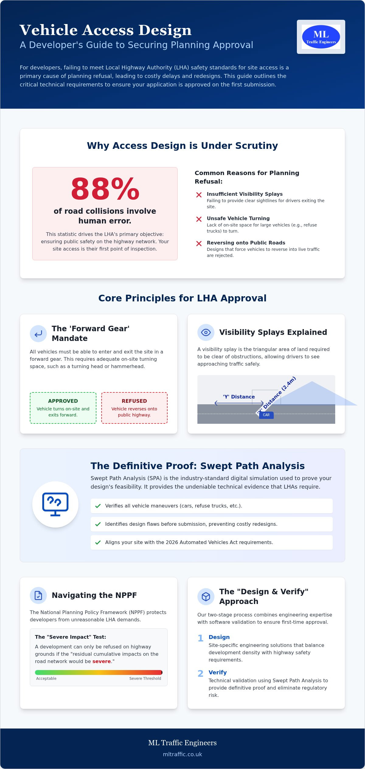
    Human error contributes to 88% of road collisions, a statistic that has pushed Local Highway Authorities in 2026 to demand unprecedented levels of technical precision. For developers, this means a standard site entrance is no longer enough to clear the planning hurdle. You likely recognize the pressure of managing tight project timelines only to face a refusal because a visibility splay is insufficient or a refuse vehicle cannot turn safely. It’s a common bottleneck that delays construction and drains resources.

    This guide ensures you master every technical requirement for a vehicle access design for planning application that secures immediate approval. We’ll provide the clarity needed to navigate complex local highway guides and the updated Design Manual for Roads and Bridges. You’ll learn how to leverage industry-standard software for Swept Path Analysis and align your site with the 2026 Automated Vehicles Act. By following these safety standards, you can transform a potential regulatory headache into a planning-ready design that satisfies every LHA requirement from the first submission.

    Key Takeaways

    • Understand why Local Highway Authorities prioritize access scrutiny and how to transition from generic templates to site-specific, justified design solutions.
    • Master the “Forward Gear” requirement and the precise calculation of visibility splays to eliminate the risk of refusal on safety grounds.
    • Utilize Swept Path Analysis as the definitive technical proof for your vehicle access design for planning application, ensuring all maneuvers are verified through digital simulation.
    • Identify the distinct requirements for Section 278 and Section 38 agreements to streamline your transition from planning approval to highway adoption.
    • Learn how a “Design and Verify” approach combines engineering expertise with industry-standard software to reduce regulatory pressure and project delays.

    The Strategic Importance of Vehicle Access Design in Planning

    Highway Officers scrutinize vehicle access design for planning application submissions before almost any other technical detail. Their primary objective is public safety. An access point that fails to meet visibility or turning standards creates a permanent liability on the public highway. In 2026, the expectation has shifted from applying generic design templates to providing site-specific, justified access solutions. This transition requires developers to use technical data and established Access Management Principles to prove that their proposed junction is both safe and efficient.

    Failing to prioritize this design early in the project lifecycle introduces significant financial risk. If a layout is finalized before the access is verified, a single objection from the Local Highway Authority (LHA) can force a complete site redesign. This results in wasted architectural fees and missed planning deadlines. Integrating your access strategy directly into your Transport Statement ensures that the technical justification is present from day one, reducing the likelihood of costly post-submission revisions.

    Highway Safety vs. Development Density

    A common conflict exists between maximizing site density and meeting highway safety requirements. Architects often seek to place units as close to the site boundary as possible to increase yield. However, this often compromises the visibility splays required by the LHA. We find that the most successful projects balance these needs early. Over-engineering a junction can be just as problematic as under-designing it; excessive road widths or unnecessarily large radii waste valuable land and can encourage higher vehicle speeds, which undermines residential safety.

    The Role of the National Planning Policy Framework (NPPF)

    The NPPF provides the legal backbone for access negotiations in England. It protects developers from arbitrary or excessive demands by the LHA by setting a high bar for refusal. In 2026, practitioners must focus on the “severe residual cumulative impacts” threshold. If a developer can prove their access design doesn’t cross this line, the LHA has limited grounds for objection. The NPPF states that development should only be prevented or refused on highways grounds if there would be an unacceptable impact on highway safety, or the residual cumulative impacts on the road network would be severe.

    Core Design Principles: Forward Gear and Visibility Splays

    Precision in a vehicle access design for planning application centers on two critical factors: how a vehicle enters and leaves the site, and what the driver can see from the junction. Local Highway Authorities (LHAs) almost universally mandate that vehicles enter and exit in a forward gear. Reversing onto a classified road, such as an A, B, or C class carriageway, is a primary reason for planning refusal. In 2026, planning inspectors continue to uphold this safety standard during appeals, viewing reversing maneuvers as an unacceptable risk to road users.

    The complexity of your access design is dictated by the road hierarchy and the potential intensification of use. If a development increases the volume or changes the type of traffic using an existing entrance, the LHA will re-evaluate the access against current safety benchmarks. This often happens in residential conversions where a domestic driveway is expected to serve multiple dwellings. To avoid delays, developers must prove that the existing geometry can handle the increased load without compromising the flow of the wider network.

    The Ingress and Egress Mandate

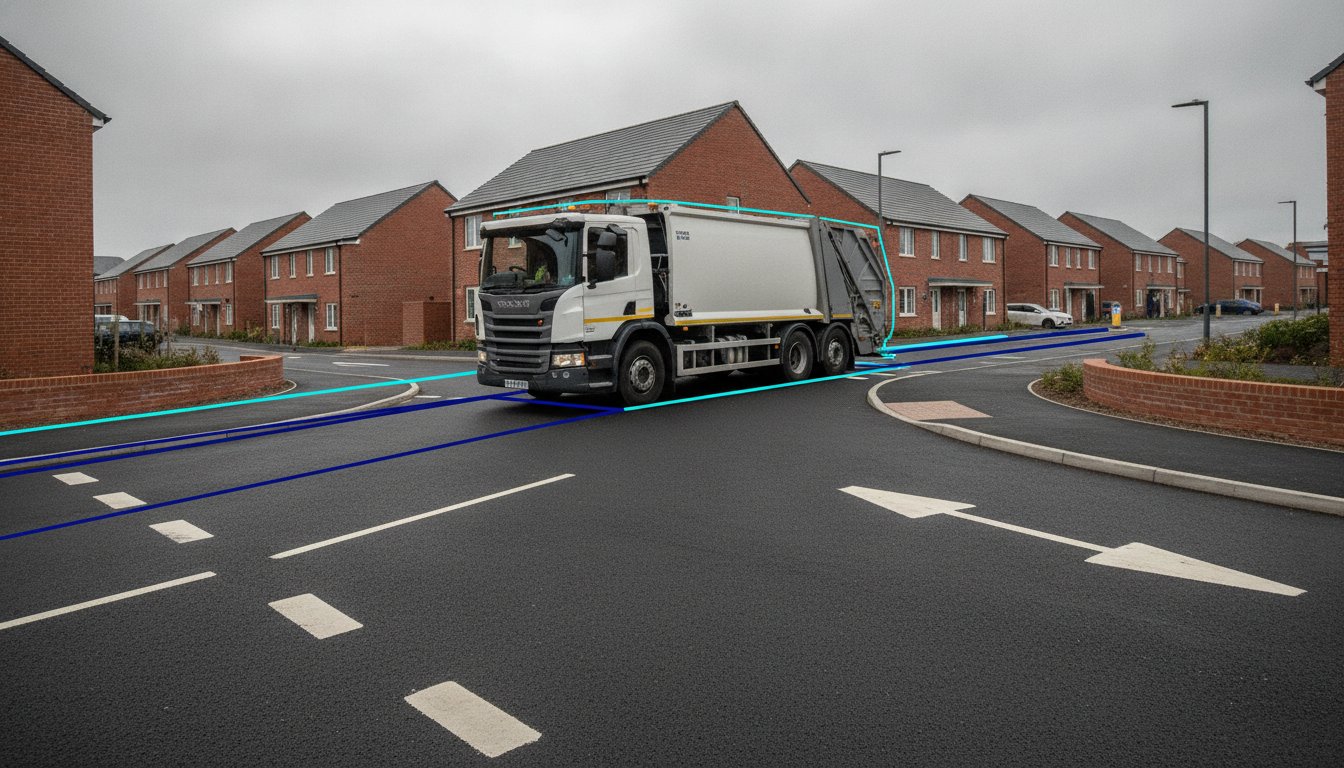
    Vehicles must have sufficient space to turn within the site boundary so they can always exit facing forward. On constrained urban plots, providing this space requires careful engineering of turning heads or hammerheads. While residential designs focus on cars and delivery vans, commercial developments must accommodate larger vehicles. If your site layout is particularly tight, performing a Swept Path Analysis during the initial design phase can identify whether your turning provision is technically feasible before you submit your application.

    Visibility Splays and Manual for Streets (MfS)

    Visibility is defined by X and Y distances. The X-distance is the driver’s set-back from the edge of the road, typically 2.4 meters. The Y-distance is the sightline length along the carriageway, which we calculate based on 85th percentile speed surveys rather than just the posted speed limit. In urban environments, we apply Manual for Streets (MfS) standards, which prioritize place-making and often allow for shorter splays. Conversely, rural or high-speed routes require the more stringent Design Manual for Roads and Bridges (DMRB) criteria.

    A common hurdle involves visibility splays crossing third-party land. If you do not control the land within the splay, the LHA will likely object because you cannot guarantee the area remains free of obstructions. You must also ensure that street furniture, signage, and landscaping are positioned outside these sightlines. Even a small planter or a misplaced lamp column can result in a non-compliant vehicle access design for planning application, leading to a swift rejection from the highway officer.

    Swept Path Analysis: The Technical Proof of Feasibility

    Highway Officers require technical proof that your proposed layout works in reality. Swept Path Analysis (SPA) provides this through digital vehicle simulation. It replaces static 2D drafting with a dynamic model of vehicle movement. This technology identifies “pinch points” where a vehicle’s body might overhang a footway or strike a boundary. For a vehicle access design for planning application, SPA is often the difference between a quick approval and a protracted dispute over feasibility. It serves as the definitive currency for highway negotiations in 2026.

    The simulation process follows a logical sequence to ensure accuracy. We start by importing your site topography and proposed layout into industry-standard software like AutoTURN. We then select the appropriate design vehicle and plot the intended maneuver path for both ingress and egress. The software generates a swept path “envelope” that shows the space occupied by the vehicle. Finally, we assess the clearances against boundary walls, lamp columns, and street furniture to verify the design’s safety.

    Choosing the Right Design Vehicle

    A successful simulation shows more than just wheel tracks. It displays the full vehicle envelope, which includes body swing and mirror clearance. We typically include a 0.5m clearance margin to satisfy safety-conscious highway engineers. This data allows us to justify narrower road widths in sustainable developments. It proves that safe vehicle access design for planning application is possible without over-engineering the infrastructure. Precision here reduces the land take for roads, which helps you maximize the usable space for units or green infrastructure.

    Securing planning for a vehicle access design for planning application requires more than just a drawing. It involves navigating the legal agreements that govern how private land connects to the public highway. In England, developers primarily deal with Section 278 and Section 38 agreements. While a Section 38 agreement focuses on the adoption of entirely new roads within a development, a Section 278 agreement is necessary for any works that alter the existing highway, such as creating a new bellmouth or widening a crossover.

    A robust submission package should include a checklist of technical documents to ensure the Highway Officer has everything needed for a formal recommendation. We recommend including:

    • Scaled site access plans showing precise geometry and visibility splays.
    • Swept Path Analysis results for critical vehicles like fire tenders or refuse trucks.
    • A Transport Assessment or Statement to justify the access location.
    • Speed survey data if you’re deviating from standard visibility requirements based on actual road speeds.
    • Drainage and lighting strategies if the access significantly changes the highway footprint.

    While demonstrating access for fire tenders is a planning necessity, ensuring the structural safety of your buildings through professional fire stopping is equally critical; you can learn more about National Fire Ltd for specialist passive fire protection services.

    Seeking pre-application advice from the Local Highway Authority (LHA) is a strategic move. It allows you to identify potential objections regarding site entrance locations before you commit to a full architectural layout. LHAs often have specific preferences for junction types that aren’t always obvious from national guidance.

    Section 278 (S278) Agreements Explained

    The S278 agreement is the legal mechanism under the Highways Act 1980 that allows developers to make permanent changes to the public road. Although formal technical approval usually occurs after planning permission is granted, you must consider the S278 requirements during the initial design. If your proposed vehicle access design for planning application doesn’t meet the LHA’s specific technical standards for construction and drainage, you may face expensive redesigns during the post-planning technical audit phase.

    Local Highway Design Guides vs. National Standards

    Every council in England maintains its own “standard details” for access points. While the Manual for Streets provides national guidance, a Borough’s design manual might specify different radii for corners or specific materials for crossovers. We often find that local standards are more rigid than national research. In cases where local requirements make a site unviable, we use evidence-based research from national documents to challenge those standards and secure a bespoke approval.

    If you need a technical partner to manage these regulatory hurdles, you can book a Transport Assessment or Swept Path Analysis to ensure your design meets both local and national benchmarks.

    Vehicle Access Design for Planning Applications: The 2026 Developer's Guide

    Expert Support for Your Access Design with ML Traffic Engineers

    Securing a vehicle access design for planning application that satisfies both your vision and the Highway Authority’s safety requirements requires a technical bridge. ML Traffic Engineers provides this bridge by combining deep engineering intuition with advanced simulation technology. Our ‘Design and Verify’ approach ensures that every site entrance is not just a drawing, but a functional, safe, and adoptable piece of infrastructure. By identifying potential highway objections early, we reduce the regulatory pressure on your team and prevent the delays that often derail high-stakes developments.

    We understand that access design doesn’t exist in a vacuum. It is a fundamental component of your wider submission. We ensure your access strategy integrates seamlessly into your Transport Statements and Travel Plans. This holistic approach provides a consistent narrative to the planning officer, demonstrating that every aspect of vehicle movement has been meticulously planned and verified. Getting a professional review of your vehicle access design for planning application before you submit to the council is the most effective way to protect your project from technical refusals.

    Why Developers Trust ML Traffic Engineers

    Since our founding in 2014, we’ve focused exclusively on providing technical reporting and analysis for projects across England. We don’t just provide data; we provide solutions. Our team has direct experience negotiating with Highway Authorities, which allows us to anticipate their concerns and address them within our reports. We pride ourselves on precision and adherence to standards, delivering clear, actionable technical documents that bridge the gap between architectural aesthetics and highway safety.

    Next Steps for Your Planning Application

    The most efficient way to move forward is to request a site-specific access feasibility study. We work directly with your architects to refine site layouts, ensuring that visibility splays and turning heads are optimized without sacrificing development density. This collaborative process ensures your layout is planning-ready from the first draft. Contact our team today for a Transport Planning Consultation to discuss your site’s specific access requirements and secure the technical proof needed for approval.

    Securing Your Site’s Future with Compliant Access Design

    A successful vehicle access design for planning application requires a precise balance of safety, technical simulation, and regulatory knowledge. Mastering the forward-gear rule and visibility splays is critical to avoiding immediate refusal from the Local Highway Authority. By utilizing advanced Swept Path Analysis, you provide the definitive proof Highway Officers need to approve your site layout. Navigating the complexities of Section 278 and Section 38 agreements early in the process ensures that your project remains viable from inception through to adoption.

    Precision is a functional necessity in this high-stakes environment. Since 2014, ML Traffic Engineers has provided professional Transport Planning Reports that act as the technical bridge between architectural vision and highway safety. Our advanced Swept Path Analysis capabilities and expertise in S278 and S38 requirements reduce the logistical pressures on your development team. Secure your planning approval with expert vehicle access design from ML Traffic Engineers. We’re ready to help you transform complex highway standards into a clear path for project success.

    Frequently Asked Questions

    Do I need planning permission for a new vehicle access on a classified road?

    Yes, you must obtain planning permission for any new vehicle access connecting to a classified road, which includes A, B, and C class carriageways. While creating an entrance on an unclassified residential street might sometimes fall under permitted development, classified routes are strictly regulated due to higher traffic volumes and speeds. Your vehicle access design for planning application must include technical evidence that the new junction doesn’t compromise the safety or flow of the existing highway network.

    What is the minimum width for a residential vehicle access in the UK?

    For a single residential dwelling, the minimum width is typically 3 meters. If the access serves multiple properties, Local Highway Authorities often require a width of 4.5 meters to 5.5 meters to allow two vehicles to pass simultaneously. These dimensions ensure that vehicles don’t have to wait on the public highway, which reduces the risk of collisions. Always check your specific council’s design guide because standard details vary between different boroughs in England.

    Why is ‘ingress and egress in forward gear’ so important for planning?

    Safety is the primary reason why Local Highway Authorities mandate that vehicles enter and exit a site in a forward gear. Reversing onto a classified road is a high-risk maneuver that significantly increases the likelihood of accidents with passing traffic or pedestrians. If your site layout doesn’t provide enough space for a vehicle to turn internally, the highway officer will likely recommend refusal. This requirement is a non-negotiable foundation of modern highway safety standards.

    How much visibility do I need for a 30mph road access?

    On a standard 30mph urban road, the Manual for Streets typically requires a visibility splay of 2.4 meters for the X-distance and 43 meters for the Y-distance. However, if a speed survey reveals that the 85th percentile speed is higher than 30mph, the required Y-distance will increase accordingly. It’s vital to measure these sightlines from a height of 1.05 meters to ensure drivers have a clear view of approaching vehicles, cyclists, and other road users.

    Can a planning application be refused solely on vehicle access grounds?

    Yes, a planning application can be refused solely on highway safety grounds if the proposed vehicle access is deemed unsafe. If the design fails to provide adequate visibility splays or lacks sufficient internal turning space, the Local Highway Authority will issue a formal objection. Under the National Planning Policy Framework, development can be prevented if the impact on highway safety is unacceptable or the residual cumulative impacts on the road network are severe.

    What vehicle should I use for my Swept Path Analysis simulation?

    The choice of vehicle depends entirely on the nature of your development. For most residential projects in England, the 11.4 meter refuse collection vehicle is the “gold standard” required by highway officers. Commercial or industrial sites usually require simulations using a 16.5 meter articulated heavy goods vehicle (HGV). Using the correct design vehicle for your vehicle access design for planning application ensures that the most restrictive maneuvers are technically verified before submission.

    What is the difference between a dropped kerb and a full vehicle access?

    A dropped kerb refers specifically to the physical alteration of the pavement to allow a vehicle to cross the footway. In contrast, a full vehicle access encompasses the legal permission and technical design of the junction where your private land meets the public highway. While a dropped kerb is a construction detail, the vehicle access includes visibility splays, drainage, and turning requirements that must be approved by the planning and highway authorities before any work begins.

    How long does it take to get highway technical approval for an access design?

    The timeline for highway technical approval varies depending on the complexity of the project. A standard planning response from the Local Highway Authority usually takes between 6 and 12 weeks. However, if your project requires a formal Section 278 agreement for works on the public highway, the technical audit and legal drafting process can take several months. Early engagement through pre-application advice is the best way to accelerate these regulatory and technical timelines.

    Michael Lee

    Article by

    Michael Lee

    Transport planner with over 35 years' experience.

    Disclaimer

    The content on mltraffic.co.uk, including all technical articles, guides, and resources, is provided for general informational and educational purposes only. It is not intended to constitute professional advice in traffic engineering, transportation planning, development approvals, or any other technical or legal field.
    While ML Traffic Engineers makes every reasonable effort to ensure the accuracy, completeness, and timeliness of the information published, we do not provide any warranties or representations (express or implied) regarding its reliability, suitability, or availability for any particular purpose. Any reliance you place on the content is strictly at your own risk.
    In no event shall ML Traffic Engineers, its directors, employees, authors, or affiliates be liable for any direct, indirect, incidental, special, consequential, or punitive damages (including, without limitation, loss of profits, data, or business opportunities) arising out of or in connection with the use of, or inability to use, any information provided on this website.
    The articles and guides on this site are not a substitute for engaging a qualified, professional traffic engineer to assess your specific project requirements. For tailored advice, compliance assessments, or traffic engineering services, please contact a competent professional.
    This disclaimer may be updated from time to time without notice. By accessing or using this website, you agree to be bound by the most current version of this disclaimer.

  • Vehicle Access Visibility Splays: The Developer’s 2026 Guide to Planning Success

    Vehicle Access Visibility Splays: The Developer’s 2026 Guide to Planning Success

    A single miscalculation in your vehicle access visibility splays can render a high-value development site undevelopable before the first brick is even laid. You likely recognize that securing Highway Authority approval remains one of the most significant risks to your project timeline. The constant tension between maximizing developable area and meeting uncompromising safety standards often leads to costly design errors and planning delays.

    This guide empowers you to master the technical requirements of X and Y distances, ensuring your site access meets the latest UK safety standards and secures planning approval without friction. We provide the professional precision necessary to navigate the complex transition between Manual for Streets and DMRB requirements. By integrating rigorous data collection early in the design phase, you can mitigate the risk of ‘unsafe access’ objections that frequently stall major applications.

    We examine the 2026 regulatory updates, the vital role of 85th percentile speed surveys in determining splay dimensions, and strategic solutions for boundary issues where sightlines cross third-party land. This technical overview ensures your project remains compliant, safe, and ready for execution.

    Key Takeaways

    • Understand how vehicle access visibility splays function as the primary safety mechanism for site access, protecting both emerging and passing motorists.
    • Master the technical application of X and Y distances to ensure your junction geometry meets precise Highway Authority stopping sight distance requirements.
    • Determine the correct regulatory framework for your site by distinguishing between Manual for Streets (MfS) and DMRB standards based on local road speeds.
    • Learn to identify and mitigate common sightline obstructions, such as boundary walls and vegetation, while adhering to strict vertical visibility limits.
    • Streamline your planning application by integrating visibility analysis with Swept Path Analysis for a comprehensive, submission-ready Transport Statement.

    What Are Vehicle Access Visibility Splays and Why Are They Critical?

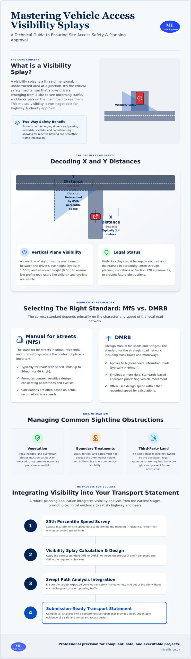
    Vehicle access visibility splays represent the physical area at a junction where sightlines must remain entirely unobstructed to ensure safe movement between a side road and a major road. Unlike a simple 2D drawing, a splay is a three-dimensional envelope of visibility. It ensures that any driver positioned at the junction has a clear, unhindered view of approaching traffic. Precision in these calculations is mandatory. Highway Authorities treat these splays as the primary gatekeepers of site viability, often prioritizing them over architectural aesthetics or unit density. A site with a ‘blind’ access point is often fundamentally undevelopable, as safety remains a non-negotiable requirement for planning approval.

    The safety benefit is strictly two-way. While it is vital for the emerging driver to see oncoming traffic, it’s equally important for drivers on the major road to see vehicles preparing to join the flow. This mutual visibility allows for reactive braking and smoother traffic integration. Adhering to standard road junction design principles ensures that all road users, including cyclists and motorcyclists, are protected from high-speed collisions. In 2026, failing to demonstrate compliant vehicle access visibility splays in your initial application is a leading cause of immediate refusal. Visibility analysis is the cornerstone of a robust Transport Statement, providing the technical evidence needed to satisfy highway engineers.

    The Geometry of Safety: Side Road vs. Major Road

    Visualizing the splay as a triangle is the most effective way to understand your site entrance. The ‘X’ distance is your setback from the major road, while the ‘Y’ distance extends along the main carriageway. The speed of the major road dictates the entire design. Higher recorded speeds require longer ‘Y’ distances to account for vehicle stopping sight distances. In urban development projects, this geometry must also account for pedestrian visibility. Drivers must be able to see pedestrians on the footway before the vehicle crosses their path. We use actual speed data, rather than just posted limits, to ensure the triangle is both safe and realistic.

    Legal and Planning Status of the Splay

    Visibility splays must be maintained in perpetuity. The Highway Authority requires long-term control over this land to prevent future obstructions like overgrown hedges or new fences. If the required splay crosses land you don’t own, you must secure that land through legal agreements or demonstrate that it’s part of the public highway. We often manage these requirements through Section 278 agreements for off-site improvements. These visibility requirements typically appear as strict planning conditions. You’ll often find that you cannot begin work on-site until the access and its associated visibility splays are physically constructed and verified.

    Decoding the Dimensions: Understanding X and Y Distances

    Precision is the difference between a validated planning application and a costly refusal. When designing vehicle access visibility splays, we define the safety area using two primary coordinates: the X and Y distances. The X distance represents the setback from the edge of the major road to the driver’s eye. While 2.4 meters is the standard requirement for most junctions, this measurement is not arbitrary. It allows a driver to see the main road clearly without their vehicle protruding into the flow of traffic. The Y distance, or Stopping Sight Distance (SSD), is the length visible along the major road. This distance must be sufficient for a driver on the main road to see a hazard and come to a safe stop.

    Technical accuracy extends into the vertical plane. We must maintain a clear line of sight between a driver’s eye height, typically 1.05 meters, and an object height of 0.6 meters. This ensures that low-profile road users, such as children or cyclists, are not obscured by boundary treatments. Environmental factors also influence these calculations. Steep gradients or road surfaces prone to moisture can increase braking distances, requiring an extension of the Y distance to maintain safety margins. Following the Manual for Streets (MfS) guidance, we calculate these dimensions based on actual vehicle deceleration rates rather than theoretical ideals.

    When Can the X Distance Be Reduced?

    Reducing the X distance to 2.0 meters is sometimes permissible for lightly trafficked residential drives or in constrained urban environments. However, Highway Authorities often resist this ‘nose-out’ visibility because it forces the front of the vehicle to enter the major road before the driver has a full view. At ML Traffic, we justify these reductions by providing empirical evidence of low traffic volumes or by using Swept Path Analysis to prove that the maneuver remains safe. If you are struggling with a tight site boundary, commissioning professional Traffic Surveys can provide the specific data needed to defend a non-standard design.

    Calculating the Y Distance: The Speed Factor

    The Y distance is directly tethered to the 85th percentile speed of the major road. A 20mph zone typically requires an SSD of 25 meters, whereas a 30mph zone requires 43 meters. It is a common error to rely solely on the posted speed limit. Actual recorded speeds often exceed the limit, and Highway Authorities will demand visibility splays that reflect how the road is used in reality. We use 85th percentile speed data to ensure your design is robust enough to pass a formal safety review.

    MfS vs. DMRB: Selecting the Right Regulatory Standard

    Selecting the correct regulatory framework is a strategic decision that dictates the viability of your site layout. In the UK, we primarily work with two sets of guidance: Manual for Streets (MfS) and the Design Manual for Roads and Bridges (DMRB). MfS is the standard for most urban and residential environments where speeds are 37mph or lower. It prioritizes place-making and utilizes stopping sight distances based on actual vehicle deceleration. Conversely, the DMRB is a more rigid standard designed for trunk roads and high-speed rural routes.

    The ‘grey area’ typically occurs on the urban fringe where a 30mph limit transitions into a 60mph zone. Applying DMRB standards to an urban-edge site often results in excessively large vehicle access visibility splays. These over-engineered designs can consume valuable frontage, reduce your unit count, and ultimately kill site density. We specialize in navigating these transitions, using technical authority to argue for the more appropriate MfS standard when the character of the road supports it. Identifying the most appropriate standard early prevents logistical pressures and ensures your project meets safety benchmarks without sacrificing land.

    The Critical Role of Speed Surveys

    Relying on posted speed limits is a common mistake that leads to conservative, space-wasting designs. We recommend conducting 85th percentile speed surveys to determine the actual speed at which motorists travel past your site. If the 85th percentile speed is lower than the limit, we can often justify shorter Y distances, preserving more of your developable area. For example, on a recent project with restricted frontage, a speed survey proved that actual speeds were significantly lower than the 30mph limit. This allowed for a reduction in the required splay, saving multiple residential units that would have otherwise been lost to visibility requirements. Professional Traffic Surveys provide the empirical data required to challenge assumptions and maximize site potential.

    National vs. Local Highway Authority Variances

    While MfS and DMRB provide national frameworks, local Highway Officers often have their own specific interpretations. Some authorities are more flexible regarding ‘nose-out’ visibility, while others strictly adhere to their own internal design guides. Early pre-application engagement is essential to understand these local nuances before you finalize your site plan. This proactive approach is particularly vital when navigating London’s transport planning system, where high-density constraints require a more tailored technical justification for every meter of visibility. We manage these negotiations on your behalf, ensuring your design aligns with both national standards and local expectations.

    Managing Obstructions and Maintenance within the Splay

    The 0.6m rule is the fundamental benchmark for any object positioned within the visibility envelope. To maintain a clear line of sight between the driver’s eye height (1.05m) and the object height (0.6m), everything within the splay must remain below this 600mm threshold. Common pitfalls include boundary walls, decorative hedges, and seasonal vegetation that grows rapidly. Parked cars represent another significant concern. Highway Authorities will often require new parking restrictions if existing or proposed on-street parking blocks the vehicle access visibility splays.

    Not every object is a prohibited obstruction. Slim signposts, lighting columns, and clear-stemmed trees where the canopy starts above 2.0m are often permitted because they don’t significantly mask a vehicle. However, the cumulative effect of multiple ‘slim’ objects can still lead to a refusal if they create a visual screen. If your site layout is constrained, we can perform a detailed assessment to identify which existing features can be retained and which must be removed to satisfy safety requirements.

    Land Ownership and Control

    For a planning application to succeed, you must demonstrate that the required visibility splays are either within your site’s red-line boundary or on land that is already part of the public highway. If a splay crosses third-party land, you face a significant legal hurdle. You must either purchase that land or secure a legal agreement with the neighbor. In some cases, we utilize Grampian conditions. These are negatively worded planning conditions that prevent development from starting until the off-site visibility is secured. We often facilitate these arrangements through Section 106 or Section 278 agreements to ensure the Highway Authority has the legal right to maintain the sightlines in perpetuity.

    Designing for Longevity

    Maintaining vehicle access visibility splays isn’t just a requirement for the planning phase; it’s a permanent safety obligation. When designing your landscaping scheme, select low-growth species that naturally stay below 0.6m. This prevents future safety breaches caused by overgrown vegetation. As the developer, you remain liable for maintaining these sightlines until the road is formally adopted by the council. For complex projects involving new road infrastructure, our Highway Design S278 & S38 Guide provides deeper insight into the adoption process and long-term maintenance requirements.

    If you’re facing boundary disputes or need a technical justification for a potential obstruction, contact us today to discuss how our Transport Statements can resolve your planning bottlenecks and secure your site’s access.

    Vehicle Access Visibility Splays: The Developer’s 2026 Guide to Planning Success

    Integrating Visibility into Your Transport Statement

    A robust Transport Statement relies on the technical validation of vehicle access visibility splays. It isn’t enough to state that an access point is safe; we must prove it through rigorous data. Our workflow begins with precise site surveys to capture 85th percentile speeds, which then inform our CAD modeling. This transition from raw data to engineered drawings ensures the Highway Officer receives a submission that is technically sound and ready for approval on the first attempt. We present our findings in a logical, sequential format that mirrors the Highway Authority’s own review process, reducing the friction often found in planning negotiations.

    There is a critical synergy between visibility analysis and Swept Path Analysis. While visibility splays ensure drivers can see, Swept Path Analysis proves that vehicles can physically maneuver through the junction without overrunning footways or striking street furniture. We integrate these two disciplines to ensure your site entrance is both visible and navigable. Presenting these reports as a unified technical package demonstrates a comprehensive understanding of junction safety. This combined approach reduces the likelihood of supplementary information requests that can stall your project for weeks.

    Beyond the Drawing: The Technical Report

    The technical report goes beyond simple geometry. We use evidence-based engineering to justify deviations from standard guidance when site constraints make literal compliance impossible. This approach is especially critical when following our Transport Assessment London Guide, where high-density environments require creative but safe solutions. Our safety-critical designs are backed by professional indemnity insurance, providing developers with the assurance that their project’s technical foundation is legally and professionally robust. We don’t just provide drawings; we provide the engineering justification needed to win planning appeals.

    Next Steps for Your 2026 Planning Application

    Early-stage feasibility is the most effective way to protect your site’s value. We recommend checking vehicle access visibility splays before you finalize your site layout. Identifying a visibility constraint during the initial design phase allows for minor adjustments to building positions or frontage treatments. Waiting until the full application stage to discover an unsafe access point often results in expensive redesigns and lost units.

    To streamline your 2026 planning application, you should request a site-specific access review as early as possible. We provide a clear roadmap from initial assessment to final Highway Authority sign-off, managing the logistical and regulatory pressures so you don’t have to. By choosing a partner that understands the intricate relationship between safety standards and commercial site viability, you ensure your project moves forward with unwavering reliability and precision.

    Securing Site Viability Through Technical Precision

    Securing planning approval in 2026 requires more than a compliant drawing; it demands an evidence-based approach to highway safety. By mastering the geometric requirements of X and Y distances and selecting the appropriate regulatory standard, you protect your development from the risk of ‘unsafe access’ refusals. Integrating these vehicle access visibility splays with detailed data collection ensures your site maximizes its developable area while meeting the Highway Authority’s stringent benchmarks. We’ve explored how speed surveys and proactive obstruction management turn regulatory hurdles into manageable design elements.

    Our team acts as your dependable technical partner, offering specialized expertise in MfS and DMRB compliance alongside comprehensive Transport Planning support. We’re highly experienced in Section 278 negotiations, ensuring that off-site improvements are handled with professional integrity. Secure your site access approval with a professional visibility analysis from ML Traffic Engineers. We provide the rapid response and precision necessary to reduce logistical pressures and keep your project on schedule. Let’s ensure your site access is safe, compliant, and ready for construction.

    Frequently Asked Questions

    What is the standard X distance for a visibility splay in the UK?

    2.4 meters is the standard X distance for the vast majority of UK road junctions. This setback represents the distance from the edge of the major road to the driver’s eye, allowing for a clear view of approaching traffic without the vehicle protruding into the carriageway. In certain constrained urban settings with low traffic speeds, some Highway Authorities may permit a reduction to 2.0 meters, though this often requires a robust technical justification.

    Can a visibility splay go over a neighbour’s land?

    A visibility splay can cross third-party land, but you must demonstrate legal control over that area to ensure it remains unobstructed. The Highway Authority requires sightlines to be maintained in perpetuity, so you’ll typically need a formal easement, a land purchase, or a Grampian planning condition. If you cannot prove the land will be kept clear, the vehicle access visibility splays will be considered ‘unprotected’ and likely lead to a planning refusal.

    What height can objects be within a visibility splay?

    Objects within the splay must generally remain below a height of 0.6 meters above the ground. This threshold ensures a clear line of sight between a driver’s eye height, which is typically 1.05 meters, and lower-profile hazards or road users. While some slim items like lighting columns or signposts are often permitted, they must not cumulatively block the driver’s field of vision.

    Do I need a visibility splay for a private driveway?

    You do need a visibility splay for a private driveway if it creates a new access or intensifies an existing one onto the public highway. Safety standards apply to all access points to prevent collisions between emerging vehicles and passing traffic. Planning officers will scrutinize the access as part of your application to ensure it doesn’t compromise the safety of the road network.

    How do I calculate the Y distance for a 30mph road?

    The Y distance for a 30mph road is typically 43 meters when following Manual for Streets (MfS) guidance. However, this distance is based on the stopping sight distance required for a vehicle traveling at the 85th percentile speed of the road. If actual recorded speeds are higher than 30mph, the required Y distance will increase to ensure drivers have enough time to react and stop safely.

    What is the difference between MfS and DMRB visibility standards?

    Manual for Streets (MfS) is designed for urban and residential environments with speeds of 37mph or less, focusing on place-making and actual driver behavior. The Design Manual for Roads and Bridges (DMRB) is a more conservative standard used for high-speed rural routes and trunk roads. Applying the stricter DMRB standards to an urban site can result in unnecessarily large splays that significantly reduce your developable land.

    Can trees be planted within a visibility splay?

    Trees can be planted within a visibility splay provided they are clear-stemmed and don’t create a visual screen. The trunk must be narrow, and the canopy should start at a minimum of 2.0 meters above ground level to keep the 0.6m to 2.0m visibility envelope clear. You must also select species that won’t grow to obstruct the splay as they mature, as you are responsible for their ongoing maintenance.

    How much does a visibility splay survey cost for a planning application?

    The cost of a visibility splay assessment varies based on the size of the site and the level of data collection required. A survey that includes 85th percentile speed data or topographical mapping will involve different requirements than a desk-based assessment. Developers should seek a tailored proposal from a specialist engineer to ensure all Highway Authority requirements are met without overspending on unnecessary surveys.

    Michael Lee

    Article by

    Michael Lee

    Transport planner with over 35 years' experience.

    Disclaimer

    The content on mltraffic.co.uk, including all technical articles, guides, and resources, is provided for general informational and educational purposes only. It is not intended to constitute professional advice in traffic engineering, transportation planning, development approvals, or any other technical or legal field.
    While ML Traffic Engineers makes every reasonable effort to ensure the accuracy, completeness, and timeliness of the information published, we do not provide any warranties or representations (express or implied) regarding its reliability, suitability, or availability for any particular purpose. Any reliance you place on the content is strictly at your own risk.
    In no event shall ML Traffic Engineers, its directors, employees, authors, or affiliates be liable for any direct, indirect, incidental, special, consequential, or punitive damages (including, without limitation, loss of profits, data, or business opportunities) arising out of or in connection with the use of, or inability to use, any information provided on this website.
    The articles and guides on this site are not a substitute for engaging a qualified, professional traffic engineer to assess your specific project requirements. For tailored advice, compliance assessments, or traffic engineering services, please contact a competent professional.
    This disclaimer may be updated from time to time without notice. By accessing or using this website, you agree to be bound by the most current version of this disclaimer.
  • Sight Line Assessment: Manual for Streets Guide

    Sight Line Assessment: Manual for Streets Guide

    What if you could satisfy a rigid Local Highway Authority while protecting your site’s developable area? Many developers view the sight line assessment manual for streets as a restrictive barrier that forces them to sacrifice density for safety. It’s a common frustration to feel that complex Stopping Sight Distance formulas are working against your project’s commercial viability.

    We understand that precision is a functional necessity in these high-stakes environments. You need a layout that maintains public safety while passing rigorous regulatory scrutiny. This guide will show you how to master the technical requirements of visibility splays to secure planning approval without highway safety objections. We’ll explore the current standards for streets with speeds below 37mph, clarify the 2.4-meter X-distance rule, and provide a clear framework for creating defensible diagrams that highway officers respect. We’ll break down the critical distinction between Manual for Streets and the updated DMRB standards. You’ll learn how to apply technical guidance accurately to develop a professional strategy for your next Transport Statement or Transport Assessment.

    Key Takeaways

    • Differentiate between Manual for Streets and DMRB requirements to ensure your visibility splays meet the specific speed thresholds required by Local Highway Authorities.
    • Master the technical calculation of X and Y distances to produce a robust sight line assessment manual for streets that maximizes your site’s developable land.
    • Identify and mitigate common urban obstructions using established visibility height rules to maintain safety without compromising site density.
    • Streamline your planning process by combining sight line assessments with Swept Path Analysis to verify junction geometry before submission.
    • Reduce the risk of costly post-approval redesigns by achieving CAD-level accuracy in your initial visibility splay diagrams.

    What is a Sight Line Assessment in Manual for Streets?

    A sight line assessment is the technical process of measuring the unobstructed view available to drivers at a junction or property access. It ensures that those emerging from a minor road can see approaching traffic clearly enough to join the main flow without causing a collision. Conducting a professional sight line assessment manual for streets is now a non-negotiable requirement for UK planning applications in 2026. Precision here is vital. A small error in calculation often leads to a highway safety objection that stalls your entire development.

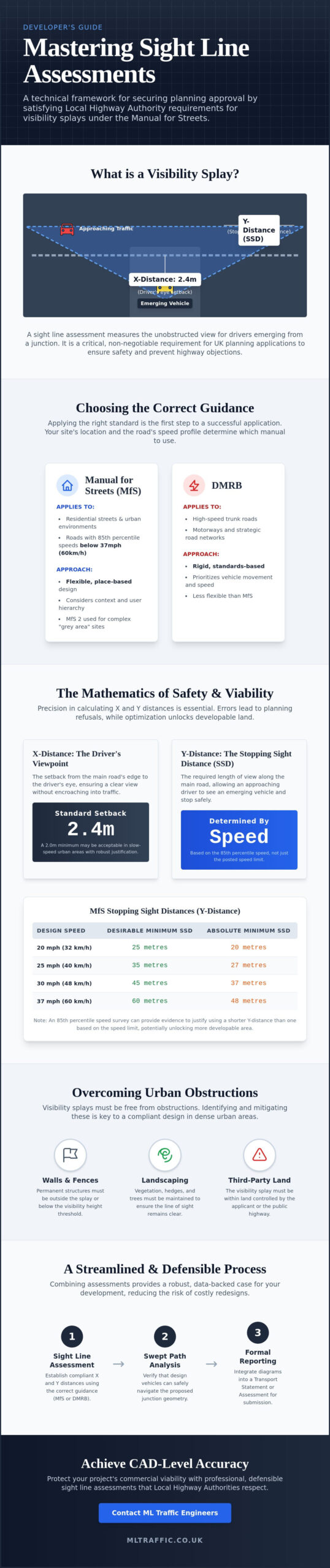
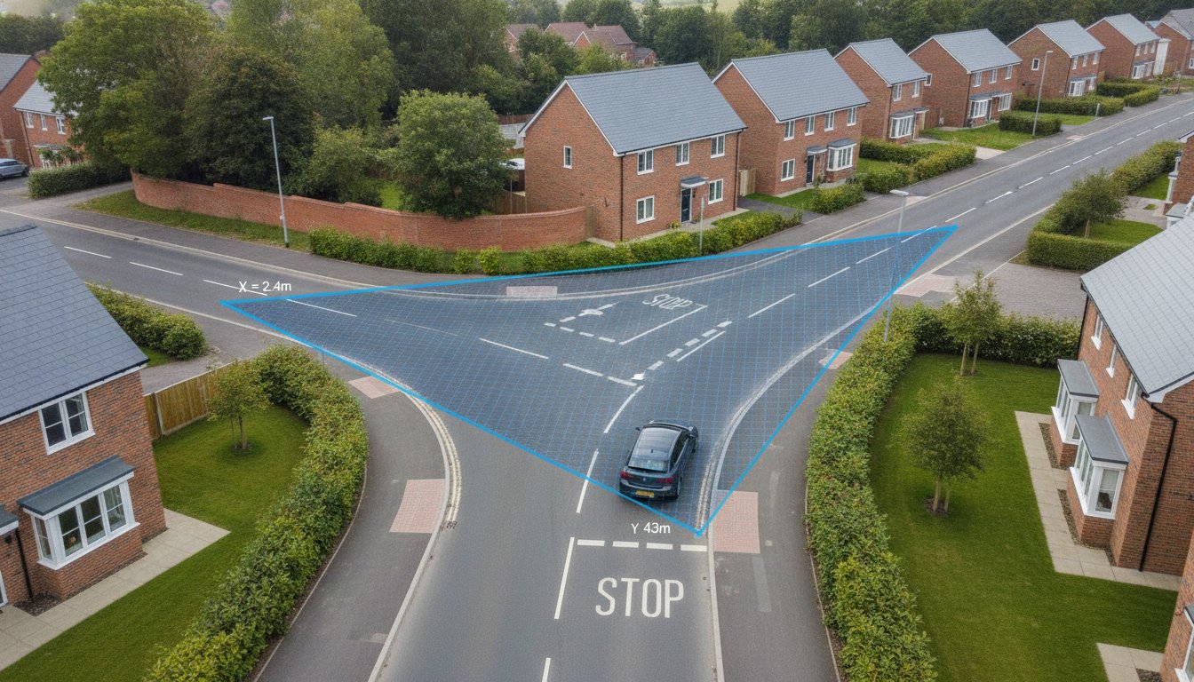
    In highway engineering, we define these visibility splays using “X” and “Y” distances. The “X” distance represents the driver’s eye position, measured back from the edge of the running carriageway. For most residential developments, 2.4 metres is the standard setback. The “Y” distance is the length of the view along the main road. This length is determined by the recorded or design speed of the traffic, known as the Stopping Sight Distance (SSD).

    Manual for Streets vs. DMRB: Which Applies to You?

    Choosing the correct guidance is the first step in any successful application. Manual for Streets (MfS) applies to residential streets and urban high streets where 85th percentile speeds are below 37mph (60km/h). If your project involves high-speed trunk roads or motorways, you must follow the Design Manual for Roads and Bridges (DMRB). While the DMRB is more rigid, MfS allows for a flexible, place-based approach. For those complex “grey area” sites that don’t fit neatly into either category, Manual for Streets 2 (MfS2) provides the necessary technical bridge to justify your design to the Local Highway Authority.

    The Legal Necessity for Visibility Splays

    Local Highway Authorities (LHA) use sight lines as a primary metric to judge the safety of a proposed access. If a splay is obstructed by third-party land or permanent structures, the LHA will likely recommend refusal on safety grounds. Under the National Planning Policy Framework (NPPF), developments must ensure safe and suitable access for all users. We integrate these assessments directly into our Transport Statements and Transport Assessments to provide the data-backed evidence planners demand. Without a clear, defensible splay diagram, your project faces significant regulatory risk.

    Calculating Visibility Splays: The X, Y, and SSD Components

    Precision is the foundation of a defensible sight line assessment manual for streets. When we calculate these splays, we aren’t just drawing triangles on a map. We’re applying mathematical certainty to ensure highway safety while protecting your site’s developable area. The visibility splay consists of three core components: the X-distance, the Y-distance, and the resulting Stopping Sight Distance (SSD). Errors in any of these three variables can lead to a planning refusal or costly Section 278 redesigns later in the project lifecycle.

    One of the most effective ways to optimise your site layout is through an 85th percentile speed survey. Many developers assume they must design for the posted speed limit. However, if actual traffic speeds are lower than the limit, a professional Traffic Survey can provide the evidence needed to justify a shorter Y-distance. This approach often unlocks land that would otherwise be lost to oversized visibility splays. We use this data to create a technical argument that Local Highway Authorities find difficult to ignore.

    Determining the Correct X-Distance

    The X-distance is the setback from the edge of the main road to the driver’s eye. In the UK, 2.4 metres is the standard setback for most residential and commercial junctions. This distance is critical because it allows a driver to see approaching traffic without the front of their vehicle protruding into the path of oncoming vehicles. While a 2.0-metre minimum is sometimes acceptable for very low-volume sites or slow-speed urban environments, it’s a “minimum” rather than a target. Using a 2.0-metre setback requires robust justification, as it can impact driver psychology and pull-out safety by forcing vehicles closer to the live carriageway.

    Mastering the Y-Distance and SSD

    The Y-distance represents the length of the splay along the main road, which must equal the Stopping Sight Distance (SSD). We use Table 7.1 from the Manual for Streets to match recorded speeds to the required visibility length. For example, at 30mph, the standard SSD is typically 43 metres. However, this calculation must account for driver eye height (1.05m to 2.0m) and object height (0.6m to 2.0m) to ensure a clear line of sight to a small child or a low vehicle. Gradients also play a major role. If the main road has a significant downhill slope, the braking distance increases, and your sight line assessment manual for streets must reflect a longer SSD to remain valid.

    Overcoming Urban Constraints and Obstructed Sight Lines

    Urban developments rarely provide a blank canvas for highway design. Most sites involve existing constraints like lamp posts, telegraph poles, or mature trees that sit directly within the required visibility area. A professional sight line assessment manual for streets must account for these real-world obstacles while maintaining safety. The standard rule dictates that the visibility splay should remain clear of obstructions between 0.6 metres and 2.0 metres above the road surface. This vertical window ensures drivers can see both low objects, like children, and taller vehicles like HGVs or buses.

    When a site is physically constrained, we don’t just accept a “fail” on the assessment. We look for technical solutions that satisfy the Local Highway Authority (LHA) without compromising the project. This often involves detailed negotiations regarding “departures from standard,” where we use data to prove that a slight reduction in splay length won’t result in a safety hazard. If you are struggling with a tight urban site, our team can help you identify these opportunities through a comprehensive Transport Assessment.

    Dealing with Street Furniture and Trees

    The “thin object” rule is a vital tool for urban designers. A single lamp post or a narrow sign pole doesn’t necessarily constitute a total failure of the splay. If the object is narrow enough, it won’t hide a vehicle or a cyclist for more than a fraction of a second. However, clusters of furniture or thick-trunked trees are significant problems. In these cases, we often recommend relocating utilities or establishing formal maintenance agreements to keep vegetation trimmed. If a splay crosses into neighbouring property, you must secure a legal easement. Without proof that you control that land, the LHA will assume the neighbour could build a wall or plant a hedge that blocks the view.

    Urban Infill Challenges

    Narrow historic streets present the greatest challenge for visibility. When standard Y-distances are impossible to achieve, we apply MfS2 principles to find a safe compromise. Footway “build-outs” are an effective solution. By extending the pavement at the junction, we move the driver’s eye further forward. This effectively increases the X-distance and improves the Y-distance without needing third-party land. Traffic calming measures can also lower 85th percentile speeds, which reduces the required SSD. Be cautious with traffic mirrors. While they seem like a quick fix, most LHAs won’t accept them as a primary safety solution due to maintenance and distortion issues. We focus on physical geometry and speed reduction to ensure your sight line assessment manual for streets stands up to scrutiny.

    Integrating Sight Lines with Transport Statements and Swept Path Analysis

    A standalone sight line assessment manual for streets provides technical data, but its true value emerges when integrated into a comprehensive Transport Statement. Planning officers rarely look at visibility splays in isolation. They evaluate how these sight lines interact with junction capacity, pedestrian crossings, and vehicle movements. We provide a holistic view of site safety by layering visibility requirements over the physical geometry of the road. This integrated approach ensures that a safe view is maintained even when the junction is operating at peak capacity.

    We use Swept Path Analysis to verify that the physical footprint of turning vehicles doesn’t overlap with the required visibility areas. If a large vehicle’s turning arc forces it to mount a verge where a visibility splay is located, the LHA will likely object. By visualising these splays in both 2D and 3D, we help planning committees understand the practical reality of the site. This clarity is essential for high-stakes presentations where technical precision can be the difference between approval and a costly deferral.

    If you need to prove your site’s safety to a Local Highway Authority, book a Transport Assessment with our expert team today.

    The Role of Speed Surveys

    Local Highway Authorities often default to the posted speed limit when assessing a site. However, the “design speed” of a road is frequently higher than the actual “driven speed” of the traffic. We conduct 7-day ATC (Automatic Traffic Counter) surveys to record actual vehicle velocities. This data allows us to justify shorter, more efficient splays based on real-world conditions rather than theoretical maximums. Presenting 7-day survey data is a powerful tool for rebutting rigid LHA objections and protecting your site’s density. A data-led sight line assessment manual for streets is far more difficult for authorities to dismiss than one based on generic assumptions.

    Combining Visibility with Access Design

    Safe access design requires that fire tenders and refuse vehicles have both the physical space to turn and a clear line of sight. Forward visibility on bends differs significantly from junction visibility; it requires a continuous check along the entire curve to ensure drivers can see stationary hazards ahead. These technical nuances are vital for projects moving into the detailed design phase. For more information on the transition from planning to construction, see our guide on Highway Design S278 & S38. Ensuring these standards are met early prevents expensive remedial works during the adoption process.

    Sight Line Assessment: Manual for Streets Guide

    Professional Sight Line Assessments with ML Traffic Engineers UK

    ML Traffic Engineers UK provides a fully managed service that takes your project from the initial topographical survey through to final planning approval. We don’t just provide equipment; we act as a comprehensive partner in your development journey. A professional sight line assessment manual for streets requires more than a simple drawing. It demands a technical lexicon and a deep understanding of regional regulations to ensure the Local Highway Authority (LHA) accepts your submission without delay. Our goal is to reduce the regulatory pressure on our clients by providing unwavering reliability and precision in every calculation.

    Our team specialises in producing ready-to-submit documentation that meets the highest industry benchmarks. By managing the full project lifecycle, we reduce the logistical pressure on your team and ensure all legislative requirements are met. We provide expert witness support and lead negotiations with rigid highway authorities who may be hesitant to accept departures from standard. This proactive approach ensures that visibility splays are defensible and optimized for site density. Our Transport Planning expertise allows us to identify potential objections before they are even raised by the council, saving you significant time and resources.

    Why Precision Matters for Your Planning Approval

    “Guestimating” visibility splays is a high-risk strategy. In a high-stakes planning environment, even a 10cm discrepancy in a splay can lead to a formal refusal on safety grounds. We use the latest CAD software to create precise Stopping Sight Distance models that reflect current standards. Precision in these drawings is a functional necessity. It prevents the need for expensive Section 278 redesigns once the project moves into the construction phase. By conducting early-stage visibility feasibility checks, we ensure your site layout is safe and commercially viable from day one.

    Get Started with ML Traffic Engineers UK

    You can request a quote for a standalone sight line assessment manual for streets or integrate this service into a wider project scope. For larger developments, we recommend combining visibility checks with a full Transport Assessment. This provides a robust, data-backed narrative that supports your application and addresses potential highway objections before they arise. Our engineers offer rapid-response technical support across England, ensuring your project remains on schedule regardless of technical hurdles. Contact our team today to secure a reliable partner for your next infrastructure project.

    Secure Your Development’s Future with Defensible Sight Lines

    Securing your development’s future relies on transforming technical hurdles into strategic advantages. By mastering the sight line assessment manual for streets, you ensure that every square metre of your site is used efficiently while maintaining the highest safety standards. Accurate calculations, as discussed throughout this guide, allow you to overcome even the most rigid highway objections. Precision in these early stages prevents costly delays and redesigns during the construction phase.

    ML Traffic Engineers UK has been a dependable partner for developers since 2014. With over a decade of planning success, we specialise in managing the full project lifecycle from initial data collection to expert technical reporting. We understand the intricate regional regulations across England, acting as a vital guardian of safety for your project. Our team provides the technical authority and unwavering reliability needed to satisfy Local Highway Authorities and protect your commercial interests.

    Don’t let highway safety objections stall your progress. Secure Your Planning Approval with a Professional Sight Line Assessment today. Our engineers are ready to deliver the precise, data-backed evidence your planning application requires for success.

    Frequently Asked Questions

    What is the standard X-distance for a residential visibility splay?

    The standard X-distance for a residential visibility splay is 2.4 metres back from the edge of the running carriageway. This setback represents the driver’s eye position and allows them to see approaching traffic without the front of their vehicle protruding into the path of oncoming cars. While a minimum of 2.0 metres is sometimes permitted for very low-volume urban mews, using the 2.4-metre standard is the most robust way to ensure safety and secure planning approval.

    Can I use Manual for Streets for a 40mph road?

    Manual for Streets is primarily designed for roads where 85th percentile speeds are 37mph (60km/h) or below. For a 40mph road, you typically must apply the Design Manual for Roads and Bridges (DMRB) standards, which require much longer visibility splays. However, Manual for Streets 2 (MfS2) provides a technical bridge that allows for some MfS principles on higher-speed non-trunk roads, provided you can demonstrate that the design remains safe for all users.

    What happens if my visibility splay crosses a neighbours land?

    You must secure a legal easement or agreement if your visibility splay crosses into land owned by a third party. Local Highway Authorities require evidence that you have permanent control over the splay area to ensure it remains clear of obstructions like walls or hedges. Without a formal agreement or a Section 106 obligation, the council will assume the visibility could be blocked in the future, leading to a planning refusal on safety grounds.

    How is Stopping Sight Distance (SSD) calculated in 2026?

    In 2026, SSD is calculated by adding the distance travelled during a driver’s reaction time to the distance required for the vehicle to come to a complete stop. A standard reaction time of 1.5 seconds is used for most urban assessments. We use Table 7.1 from the sight line assessment manual for streets to determine the base SSD, then adjust the final figure based on recorded 85th percentile speeds and the gradient of the road.

    Do I need a topographical survey for a sight line assessment?

    A topographical survey is essential for a precise sight line assessment because it captures existing gradients, kerb lines, and physical obstructions with millimetre accuracy. Relying on OS mapping alone often leads to inaccuracies that can cause a site to fail highway scrutiny. Our engineers use these detailed surveys to build CAD-accurate models of the visibility splays, providing a defensible basis for your planning application and preventing issues during the adoption phase.

    Will a lamp post in my visibility splay lead to a planning refusal?

    A single lamp post doesn’t automatically lead to a planning refusal due to the “thin object” rule. If the obstruction is narrow, it doesn’t significantly block a driver’s view of an approaching vehicle or cyclist for a dangerous amount of time. However, multiple posts or thick trees that create a continuous blind spot are major issues. We evaluate each obstruction individually to determine if it can remain or if relocation is necessary to satisfy the LHA.

    What is the difference between junction visibility and forward visibility?

    Junction visibility refers to the view available to a driver emerging from a side road onto a main road, defined by specific X and Y distances. Forward visibility is the distance a driver can see ahead while travelling along a road, particularly around bends or over crests. Both are critical components of a sight line assessment manual for streets and must be verified to ensure that drivers have enough time to react to stationary hazards.

    How much does a professional sight line assessment cost for a small development?

    The cost of a professional sight line assessment varies depending on site complexity, the number of access points, and whether an automatic traffic counter survey is required. Small developments often find it more cost-effective to integrate this check into a wider Transport Statement or Transport Assessment. You should check with a specialist traffic engineering firm for a tailored quote that reflects the specific safety and regulatory requirements of your local authority.

    Michael Lee

    Article by

    Michael Lee

    Transport planner with over 35 years' experience.

    Disclaimer

    The content on mltraffic.co.uk, including all technical articles, guides, and resources, is provided for general informational and educational purposes only. It is not intended to constitute professional advice in traffic engineering, transportation planning, development approvals, or any other technical or legal field.
    While ML Traffic Engineers makes every reasonable effort to ensure the accuracy, completeness, and timeliness of the information published, we do not provide any warranties or representations (express or implied) regarding its reliability, suitability, or availability for any particular purpose. Any reliance you place on the content is strictly at your own risk.
    In no event shall ML Traffic Engineers, its directors, employees, authors, or affiliates be liable for any direct, indirect, incidental, special, consequential, or punitive damages (including, without limitation, loss of profits, data, or business opportunities) arising out of or in connection with the use of, or inability to use, any information provided on this website.
    The articles and guides on this site are not a substitute for engaging a qualified, professional traffic engineer to assess your specific project requirements. For tailored advice, compliance assessments, or traffic engineering services, please contact a competent professional.
    This disclaimer may be updated from time to time without notice. By accessing or using this website, you agree to be bound by the most current version of this disclaimer.