
A visibility splay built up area issue can look deceptively simple on a planning drawing: two lines, a triangle, job done. In practice, it is often one of the first things a highway officer, transport consultant, or planning lawyer will scrutinise when a proposed access sits on an urban street. And for good reason. In built-up areas, drivers are not just looking for approaching cars. They are reading a much busier scene, parked vehicles, cyclists, pedestrians stepping off kerbs, delivery vans, bus stops, trees, signs, and tight frontage boundaries.
That is why visibility splays remain a central part of UK planning and access design in 2026. The question is rarely just whether a textbook splay can be drawn. The real question is whether the proposed access provides sufficient inter-visibility, for the actual speeds and conditions on site, under the standards the local highway authority expects us to use.
We see this regularly when preparing transport statements, access appraisals and technical notes for planning applications. A site can appear constrained at first glance, yet become acceptable once measured speeds, boundary alterations, parking controls, or a realistic interpretation of urban guidance are brought into the assessment. Equally, some schemes look straightforward until a topographical survey reveals the obvious problem: the hedge, cabinet or parked-car pattern that blocks the critical line of sight.
In this guide, we break down what visibility splays mean in a built-up area, the UK standards that matter, how measurements are made, when reduced splays may still be accepted, and what usually makes or breaks an application.
What A Visibility Splay Is And Why It Matters In A Built-Up Area
A visibility splay is the clear area at a junction or access that allows drivers to see, and be seen by, traffic on the main road in sufficient time to stop safely. Most often, it is shown as a triangular envelope formed from the driver’s eye position on the minor arm and the required sight distance along the major road.
At a practical level, the point is simple: if a driver emerging from a site cannot see an approaching vehicle, cyclist, or in some cases a pedestrian moving through the conflict area, the risk of collision rises sharply. That matters on every road type, but in a built-up area the stakes are slightly different from a rural access. Speeds are usually lower, yet the street is far more complex.
Urban collision risk is shaped by clutter and activity as much as by speed. A residential or mixed-use street can have parked cars close to the junction, narrow footways, frequent crossings, bins on collection day, and people moving unpredictably. So when we assess a visibility splay in a built-up area, we are not just testing a geometric standard in isolation. We are asking whether the access works safely in a real street environment.
This is also why planning decisions often turn on evidence, not assumptions. A clean drawing that ignores existing obstructions is weak. A well-supported appraisal that ties the splay to surveyed kerb lines, actual highway conditions and observed speed environment is much stronger. For councils, developers and project teams alike, visibility splays are hence both a safety issue and a planning risk issue.
How Built-Up Areas Change Visibility Requirements
Built-up areas change the way visibility is assessed because the road environment is usually slower, tighter and more heavily used by people outside vehicles. That combination shifts the analysis away from a one-size-fits-all highway standard and towards a more contextual judgement.
The biggest change is speed. On urban streets, the posted limit may be 30 mph, but actual 85th percentile speeds are often materially lower because of frontage activity, parking, traffic calming, carriageway width or junction frequency. Under Manual for Streets principles, those lower observed speeds can justify shorter Y distances than older, more conservative assumptions. That can make the difference between a site being deliverable or not.
But lower speed does not mean lower scrutiny. In fact, built-up areas often require more nuanced evidence because the street contains pedestrians, cyclists and turning movements in close proximity. A splay that may be numerically acceptable can still be questioned if it fails to account for a crossing desire line, a school route, a bus stop, or regular parking stress outside the site.
Another urban complication is that some obstruction within the wider splay envelope is normal. On-street parking, lighting columns and street trees are not unusual exceptions: they are part of the street scene. Many authorities recognise this and may accept a degree of encroachment where it does not materially compromise safety, particularly on low-speed roads. Even so, that acceptance usually depends on showing the context clearly and explaining why the residual risk remains acceptable.
In short, urban visibility requirements are often more flexible than rural ones, but they are rarely more casual.
The Main UK Standards Used To Assess Visibility Splays
In UK planning work, visibility splay assessments usually sit within three overlapping frameworks: Manual for Streets, Manual for Streets 2, DMRB, and the local authority’s own highway design guidance. The challenge is not simply knowing these documents exist. It is understanding which one carries the most weight for the road and access in question.
For most built-up area schemes, highway officers expect us to justify both the standard selected and the way it has been applied to the local context. That is where many weak reports fall down. They cite a table, but not the reason the table is appropriate.
Manual For Streets And Manual For Streets 2
Manual for Streets, published in 2007, remains the key point of reference for lower-speed streets in urban areas. Its significance was not just technical: it shifted design thinking from a purely movement-led approach to one that balances movement with place. That matters in towns and cities where roads serve homes, shops, schools and public life, not merely vehicle throughput.
For visibility splays, MfS allows sight distances to be linked to actual measured speeds, typically using 85th percentile speeds. That is why it often supports shorter Y distances than older standards would have required. On a genuinely low-speed street, that flexibility is entirely rational.
Manual for Streets also acknowledges something every practitioner knows: parking within visibility areas is common in built-up locations and does not automatically create a safety problem. The surrounding geometry, approach speed, and street function all matter.
MfS2, published in 2010, did not replace MfS so much as broaden and clarify its application, especially on somewhat busier urban roads. In practice, we use MfS and MfS2 together when arguing a place-sensitive approach to visibility on non-strategic streets.
DMRB, Local Guidance, And Planning Authority Expectations
DMRB is generally associated with strategic roads, higher-speed roads and more movement-focused design. Yet it still appears frequently in planning discussions, particularly where a site access fronts an A-road, a principal route, or any highway authority network where officers expect a stopping sight distance approach.
A typical DMRB-style assessment uses a driver eye height of 1.05 m and an object height of 0.26 m for stopping sight distance. In built-up areas, some authorities still refer back to these parameters even where MfS principles might seem relevant. That can create friction unless the transport report explains clearly why one methodology is more suitable than the other.
Then there is local guidance. County and unitary authorities often publish design guides that translate national principles into local requirements: standard X distances, Y distances by measured speed, visibility envelopes, and expectations for vertical as well as horizontal sight lines. In real planning work, these local documents often carry enormous weight.
So the practical rule is this: national standards provide the framework, but local highway authority expectations usually determine what is acceptable in an application. At ML Traffic, that is why we tailor each visibility review to the authority’s thresholds, preferred guidance and decision-making history rather than relying on a generic template.
How X Distance And Y Distance Are Measured In Practice
Most disagreements about visibility splays are not theoretical. They arise from how the geometry has actually been measured.
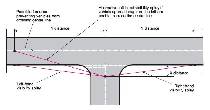
X distance is the set-back from which the emerging driver is assumed to wait and look. It is measured back from the nearside edge of the major-road carriageway along the centreline of the minor arm, or in some local guidance from the rear of footway depending on layout. A common value for residential access is 2.4 m, while 4.5 m may be expected for larger, commercial or industrial accesses where the driver position is farther back.
Y distance is measured along the nearside edge of the major road from the point where the minor access meets it. This is the distance over which the driver at the X point must be able to see approaching traffic.
That sounds neat on paper. On site, but, details matter. We need accurate kerb lines, carriageway width, footway widths, radii, gradients and boundary positions. A splay drawn from an OS base rather than a proper topographical survey is often unreliable, especially on older urban streets where kerb geometry is irregular.
Height also matters. Authorities commonly require the visibility area to be clear of obstructions above around 1.0 m, though some define the relevant envelope differently, for example between 0.6 m and 2.0 m. This is why walls, fences, hedges, signs and cabinets need to be surveyed with positions and heights, not merely sketched.
And where there is a gradient or crest, vertical visibility must be checked too. In those cases, a plan-only drawing may tell only half the story.
Typical Constraints In Urban Streets
Urban visibility splay work is often an exercise in dealing with everything that exists before the development arrives. The technical standard may be clear enough, but the surrounding street seldom is.
The usual constraints are familiar: buildings close to the back of footway, narrow frontages, limited highway land, mature landscaping, kerbside parking, and a street pattern that evolved long before current design guidance. Even small junction alterations can become contentious when there is little physical room to achieve standard splays without affecting neighbouring property or public realm.
Parked Vehicles, Street Furniture, And Boundary Treatments
Parked vehicles are probably the most common urban issue. A standard visibility triangle may cut straight through lengths of kerb that are regularly occupied, particularly near terraced housing, shops or schools. In some cases, that is fatal to the proposal. In others, authorities may accept the reality of occasional parking if speeds are low and collision risk is demonstrably limited.
Street furniture creates a different kind of problem. Lighting columns, signs, cabinets, bus shelters, bins and guardrailing can all obstruct critical lines of sight, even if they look minor on a layout plan. Trees are more nuanced: clear-stemmed trees may be acceptable, while low canopies or dense planting often are not.
Boundary treatments are another recurring pinch point. A 1.8 m brick wall might give privacy and acoustic benefit, but if it sits inside the splay envelope it can block the driver’s view entirely. Often the most efficient mitigation is simply to reduce, set back or redesign the boundary, for example by switching from a solid wall to railings above a low plinth.
Junction Geometry, Bends, Gradients, And Pedestrian Activity
Not all visibility problems are caused by objects. Sometimes the street geometry itself is the obstacle.
A bend on the major road can shorten effective sight distance well below what a straight-line plan suggests. A crest or sag can affect vertical visibility. Tight radii can alter the emerging driver’s position. And on heavily trafficked urban streets, the access may need to function safely not just for vehicle-to-vehicle conflicts but for driver awareness of pedestrians and cyclists moving across the mouth of the junction.
This matters especially near schools, local centres and public transport stops, where pedestrian activity can be intense. A technically compliant vehicle splay is less convincing if the design encourages vehicles to edge across the footway before drivers can see who is using it.
That is why robust urban assessments go beyond a flat triangle. We need to understand how the road curves, rises, narrows, and is actually used through the day. Sometimes the drawing says “compliant” while the street says “not so fast”.
When A Substandard Visibility Splay May Still Be Accepted
A substandard visibility splay is not automatically unacceptable. In built-up areas, planning and highway authorities will sometimes accept reduced visibility where the evidence shows that risk remains acceptable in context.
The strongest basis for that argument is often measured speed. If the posted limit is 30 mph but the 85th percentile speed is, say, closer to the low 20s because of parking, frontage activity or traffic calming, then a shorter Y distance may be entirely consistent with Manual for Streets principles and local guidance.
Other factors can help. Low traffic volume on the major road, one-way operation, constrained geometry that naturally slows turning speeds, or an access serving only a small number of dwellings can all support a more flexible view. Heritage constraints also matter. If a listed wall or established building line makes a standard splay impossible, authorities may look more closely at whether the actual safety effect is acceptable rather than insisting on a theoretical ideal.
That said, reduced splays are rarely accepted on assertion alone. We usually need a package of evidence: speed data, clear survey drawings, collision context where available, details of parking behaviour, and often some form of mitigation. The case becomes stronger if the proposal also improves the existing situation, even if it does not reach a full standard.
There is a legal and planning dimension here too. Appeals and committee decisions often turn on whether the authority can show a severe or unacceptable residual impact, not merely a technical shortfall. A substandard splay that is well evidenced and sensibly mitigated can hence be defensible. A poor-quality assessment with optimistic assumptions usually is not.
What To Include In A Planning Application Or Transport Report
If visibility is likely to be a live issue, the application material needs to be complete from the outset. Missing evidence is one of the easiest ways to trigger delay, objections or a request for further information.
At minimum, we would normally include:
- a scaled plan showing the proposed access and the X and Y splays:
- surveyed kerb lines, carriageway edges, footways, verges and centreline geometry where relevant:
- all potential obstructions within the visibility envelope, with positions and heights:
- a clear statement of the standards used, MfS, MfS2, DMRB, local guidance, or a justified combination:
- speed survey data where reduced Y distances are proposed or where actual speed is central to the argument:
- photographs that match the technical appraisal and help officers understand the site quickly.
For constrained sites, the report should also explain what has been tested and why certain options are not feasible. That may include rejected access positions, boundary amendments, parking restrictions, or the reason a 2.4 m X distance has been used in place of 4.5 m.
If the geometry is unusual, swept-path analysis may be needed to show that vehicles can enter and leave without awkward manoeuvres that undermine the visibility assumptions. And if the road alignment rises or bends, a vertical visibility check can be just as important as the plan drawing.
The broader point is that a planning visibility assessment should read like a reasoned professional judgement, not a pasted standard detail. Concise is fine. Thin is not.
How To Improve A Visibility Splay On A Constrained Site
Improving a visibility splay on a tight urban site is usually about small, targeted moves rather than one dramatic fix. The right answer depends on what is actually causing the restriction.
A common step is to review the X distance. If an initial design assumes 4.5 m but the access is residential in character, moving to 2.4 m may bring the driver’s eye point closer to the main road and materially improve the available Y distance. That sounds modest, but on a narrow frontage it can transform the geometry.
Boundary treatment is often next. Lowering a wall, cutting back a hedge, replacing close-board fencing with railings, or setting the boundary behind the required envelope can clear the critical sight line without changing the access location. These are sometimes the cheapest changes and, oddly enough, the ones overlooked most often early on.
Where street furniture is the issue, discussions with the highway authority may allow relocation of a sign, cabinet or pole. That is not always easy, but it can be feasible if the obstruction is singular and the benefit is clear.
Parking management is another powerful tool. If the critical problem is vehicles habitually parking across the key part of the splay, yellow lines, bollards, planters or a build-out may protect the visibility envelope. Authorities are more receptive to this where the restrictions are limited and clearly linked to access safety.
Finally, speed reduction can support a better outcome. If the street environment can be calmed, or if existing calming already keeps speeds low, the required Y distance may reduce accordingly under the relevant guidance.
On difficult sites, we often test several combinations in sequence. The best solution is usually the one that is technically defensible, affordable, and realistic for the planning authority to accept.
Conclusion
Visibility splays in built-up areas are rarely just a drafting exercise. They sit at the junction of highway safety, planning judgement and real-world street conditions. In 2026, the key to a credible assessment is still the same: use the right standard for the road, base the analysis on accurate survey information, and relate the required X and Y distances to the actual speed and activity environment.
For urban schemes, that usually means working carefully through MfS, MfS2, DMRB and local authority guidance rather than treating any one document as universally decisive. It also means being honest about constraints, parking, walls, bends, gradients, pedestrian flows, and then showing how those constraints are mitigated or why a reduced but evidence-based splay remains acceptable.
Where applications succeed, it is often because the transport evidence is practical, local and proportionate. That is the approach we favour: clear drawings, measured data, realistic design fixes and reporting that aligns with what decision-makers actually need. On constrained sites, that can make all the difference between a technical objection and a workable planning consent.
Visibility Splay in Built-Up Areas: Frequently Asked Questions
What is a visibility splay in a built-up area and why is it important?
A visibility splay is the clear triangular area at a junction or access allowing drivers to see and be seen by traffic on the main road, ensuring vehicles can stop safely. In built-up areas, it is vital due to lower speeds and complex street activity involving pedestrians and cyclists to reduce collision risks.
How do built-up areas affect visibility splay requirements compared to rural locations?
Built-up areas usually have lower vehicle speeds and more street activity like parking, pedestrians, and cyclists. This allows for potentially shorter Y distances based on measured 85th percentile speeds and some acceptance of parking within splays if safety is maintained, unlike the more rigid standards used in rural areas.
Which UK standards are used to assess visibility splays in urban areas?
Visibility splays in built-up areas are assessed mainly using Manual for Streets (MfS), Manual for Streets 2 (MfS2), the Design Manual for Roads and Bridges (DMRB), and local highway authority design guides. Choice depends on road type and local expectations, which often require evidence-based justifications.
How are the X and Y distances defined and measured for a visibility splay?
The X distance is the set-back from the major road where the driver waits, typically 2.4 m for residential accesses and 4.5 m for commercial sites, measured along the minor arm’s centreline. The Y distance is measured along the nearside edge of the main road from the junction, representing the sight distance needed for safe vehicle visibility.
Can substandard visibility splays be accepted in built-up areas?
Yes. Planning authorities may accept reduced splays if supported by evidence such as lower actual traffic speeds, traffic calming, low volumes, or physical constraints. A comprehensive safety assessment and mitigation measures often underpin acceptance of substandard splays.
What practical steps can improve a visibility splay on a constrained urban site?
Common improvements include reducing X distance to bring the driver closer to the road, setting back or lowering boundary walls and hedges, relocating obstructive street furniture, implementing parking controls to prevent vehicles blocking sight lines, and introducing speed-reducing measures to justify shorter Y distances.