A single miscalculation in your vehicle access visibility splays can render a high-value development site undevelopable before the first brick is even laid. You likely recognize that securing Highway Authority approval remains one of the most significant risks to your project timeline. The constant tension between maximizing developable area and meeting uncompromising safety standards often leads to costly design errors and planning delays.
This guide empowers you to master the technical requirements of X and Y distances, ensuring your site access meets the latest UK safety standards and secures planning approval without friction. We provide the professional precision necessary to navigate the complex transition between Manual for Streets and DMRB requirements. By integrating rigorous data collection early in the design phase, you can mitigate the risk of ‘unsafe access’ objections that frequently stall major applications.
We examine the 2026 regulatory updates, the vital role of 85th percentile speed surveys in determining splay dimensions, and strategic solutions for boundary issues where sightlines cross third-party land. This technical overview ensures your project remains compliant, safe, and ready for execution.
Key Takeaways
- Understand how vehicle access visibility splays function as the primary safety mechanism for site access, protecting both emerging and passing motorists.
- Master the technical application of X and Y distances to ensure your junction geometry meets precise Highway Authority stopping sight distance requirements.
- Determine the correct regulatory framework for your site by distinguishing between Manual for Streets (MfS) and DMRB standards based on local road speeds.
- Learn to identify and mitigate common sightline obstructions, such as boundary walls and vegetation, while adhering to strict vertical visibility limits.
- Streamline your planning application by integrating visibility analysis with Swept Path Analysis for a comprehensive, submission-ready Transport Statement.
What Are Vehicle Access Visibility Splays and Why Are They Critical?
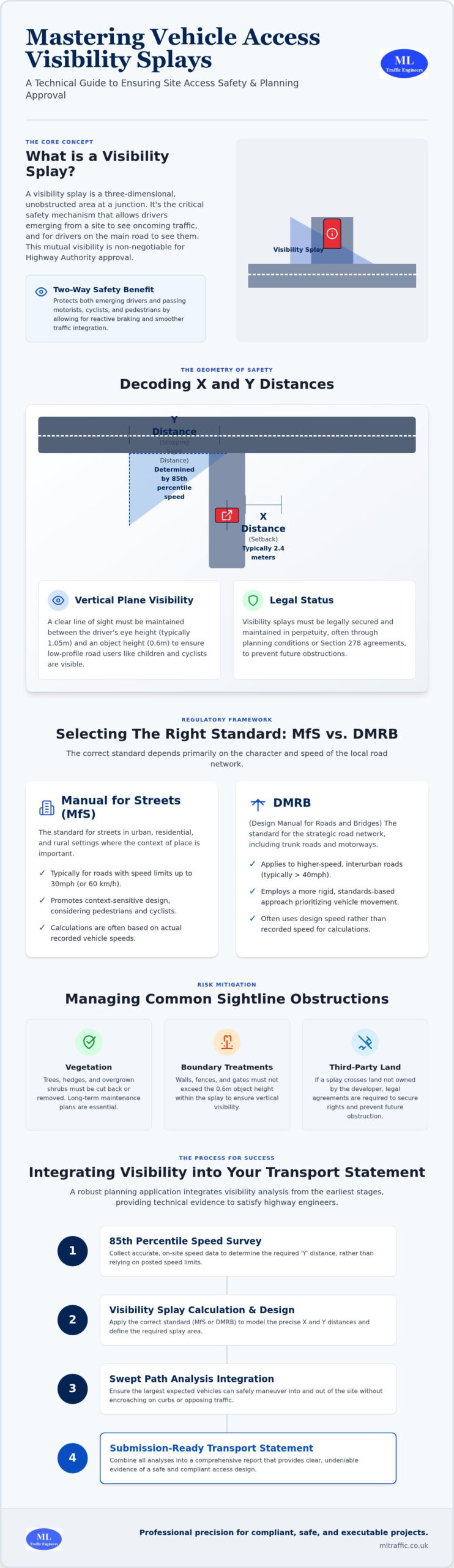
Vehicle access visibility splays represent the physical area at a junction where sightlines must remain entirely unobstructed to ensure safe movement between a side road and a major road. Unlike a simple 2D drawing, a splay is a three-dimensional envelope of visibility. It ensures that any driver positioned at the junction has a clear, unhindered view of approaching traffic. Precision in these calculations is mandatory. Highway Authorities treat these splays as the primary gatekeepers of site viability, often prioritizing them over architectural aesthetics or unit density. A site with a ‘blind’ access point is often fundamentally undevelopable, as safety remains a non-negotiable requirement for planning approval.
The safety benefit is strictly two-way. While it is vital for the emerging driver to see oncoming traffic, it’s equally important for drivers on the major road to see vehicles preparing to join the flow. This mutual visibility allows for reactive braking and smoother traffic integration. Adhering to standard road junction design principles ensures that all road users, including cyclists and motorcyclists, are protected from high-speed collisions. In 2026, failing to demonstrate compliant vehicle access visibility splays in your initial application is a leading cause of immediate refusal. Visibility analysis is the cornerstone of a robust Transport Statement, providing the technical evidence needed to satisfy highway engineers.
The Geometry of Safety: Side Road vs. Major Road
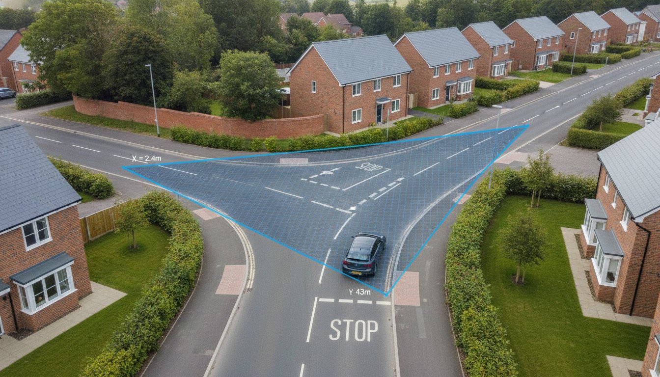
Visualizing the splay as a triangle is the most effective way to understand your site entrance. The ‘X’ distance is your setback from the major road, while the ‘Y’ distance extends along the main carriageway. The speed of the major road dictates the entire design. Higher recorded speeds require longer ‘Y’ distances to account for vehicle stopping sight distances. In urban development projects, this geometry must also account for pedestrian visibility. Drivers must be able to see pedestrians on the footway before the vehicle crosses their path. We use actual speed data, rather than just posted limits, to ensure the triangle is both safe and realistic.
Legal and Planning Status of the Splay
Visibility splays must be maintained in perpetuity. The Highway Authority requires long-term control over this land to prevent future obstructions like overgrown hedges or new fences. If the required splay crosses land you don’t own, you must secure that land through legal agreements or demonstrate that it’s part of the public highway. We often manage these requirements through Section 278 agreements for off-site improvements. These visibility requirements typically appear as strict planning conditions. You’ll often find that you cannot begin work on-site until the access and its associated visibility splays are physically constructed and verified.
Decoding the Dimensions: Understanding X and Y Distances
Precision is the difference between a validated planning application and a costly refusal. When designing vehicle access visibility splays, we define the safety area using two primary coordinates: the X and Y distances. The X distance represents the setback from the edge of the major road to the driver’s eye. While 2.4 meters is the standard requirement for most junctions, this measurement is not arbitrary. It allows a driver to see the main road clearly without their vehicle protruding into the flow of traffic. The Y distance, or Stopping Sight Distance (SSD), is the length visible along the major road. This distance must be sufficient for a driver on the main road to see a hazard and come to a safe stop.
Technical accuracy extends into the vertical plane. We must maintain a clear line of sight between a driver’s eye height, typically 1.05 meters, and an object height of 0.6 meters. This ensures that low-profile road users, such as children or cyclists, are not obscured by boundary treatments. Environmental factors also influence these calculations. Steep gradients or road surfaces prone to moisture can increase braking distances, requiring an extension of the Y distance to maintain safety margins. Following the Manual for Streets (MfS) guidance, we calculate these dimensions based on actual vehicle deceleration rates rather than theoretical ideals.
When Can the X Distance Be Reduced?
Reducing the X distance to 2.0 meters is sometimes permissible for lightly trafficked residential drives or in constrained urban environments. However, Highway Authorities often resist this ‘nose-out’ visibility because it forces the front of the vehicle to enter the major road before the driver has a full view. At ML Traffic, we justify these reductions by providing empirical evidence of low traffic volumes or by using Swept Path Analysis to prove that the maneuver remains safe. If you are struggling with a tight site boundary, commissioning professional Traffic Surveys can provide the specific data needed to defend a non-standard design.
Calculating the Y Distance: The Speed Factor
The Y distance is directly tethered to the 85th percentile speed of the major road. A 20mph zone typically requires an SSD of 25 meters, whereas a 30mph zone requires 43 meters. It is a common error to rely solely on the posted speed limit. Actual recorded speeds often exceed the limit, and Highway Authorities will demand visibility splays that reflect how the road is used in reality. We use 85th percentile speed data to ensure your design is robust enough to pass a formal safety review.
MfS vs. DMRB: Selecting the Right Regulatory Standard
Selecting the correct regulatory framework is a strategic decision that dictates the viability of your site layout. In the UK, we primarily work with two sets of guidance: Manual for Streets (MfS) and the Design Manual for Roads and Bridges (DMRB). MfS is the standard for most urban and residential environments where speeds are 37mph or lower. It prioritizes place-making and utilizes stopping sight distances based on actual vehicle deceleration. Conversely, the DMRB is a more rigid standard designed for trunk roads and high-speed rural routes.
The ‘grey area’ typically occurs on the urban fringe where a 30mph limit transitions into a 60mph zone. Applying DMRB standards to an urban-edge site often results in excessively large vehicle access visibility splays. These over-engineered designs can consume valuable frontage, reduce your unit count, and ultimately kill site density. We specialize in navigating these transitions, using technical authority to argue for the more appropriate MfS standard when the character of the road supports it. Identifying the most appropriate standard early prevents logistical pressures and ensures your project meets safety benchmarks without sacrificing land.
The Critical Role of Speed Surveys
Relying on posted speed limits is a common mistake that leads to conservative, space-wasting designs. We recommend conducting 85th percentile speed surveys to determine the actual speed at which motorists travel past your site. If the 85th percentile speed is lower than the limit, we can often justify shorter Y distances, preserving more of your developable area. For example, on a recent project with restricted frontage, a speed survey proved that actual speeds were significantly lower than the 30mph limit. This allowed for a reduction in the required splay, saving multiple residential units that would have otherwise been lost to visibility requirements. Professional Traffic Surveys provide the empirical data required to challenge assumptions and maximize site potential.
National vs. Local Highway Authority Variances
While MfS and DMRB provide national frameworks, local Highway Officers often have their own specific interpretations. Some authorities are more flexible regarding ‘nose-out’ visibility, while others strictly adhere to their own internal design guides. Early pre-application engagement is essential to understand these local nuances before you finalize your site plan. This proactive approach is particularly vital when navigating London’s transport planning system, where high-density constraints require a more tailored technical justification for every meter of visibility. We manage these negotiations on your behalf, ensuring your design aligns with both national standards and local expectations.
Managing Obstructions and Maintenance within the Splay
The 0.6m rule is the fundamental benchmark for any object positioned within the visibility envelope. To maintain a clear line of sight between the driver’s eye height (1.05m) and the object height (0.6m), everything within the splay must remain below this 600mm threshold. Common pitfalls include boundary walls, decorative hedges, and seasonal vegetation that grows rapidly. Parked cars represent another significant concern. Highway Authorities will often require new parking restrictions if existing or proposed on-street parking blocks the vehicle access visibility splays.
Not every object is a prohibited obstruction. Slim signposts, lighting columns, and clear-stemmed trees where the canopy starts above 2.0m are often permitted because they don’t significantly mask a vehicle. However, the cumulative effect of multiple ‘slim’ objects can still lead to a refusal if they create a visual screen. If your site layout is constrained, we can perform a detailed assessment to identify which existing features can be retained and which must be removed to satisfy safety requirements.
Land Ownership and Control
For a planning application to succeed, you must demonstrate that the required visibility splays are either within your site’s red-line boundary or on land that is already part of the public highway. If a splay crosses third-party land, you face a significant legal hurdle. You must either purchase that land or secure a legal agreement with the neighbor. In some cases, we utilize Grampian conditions. These are negatively worded planning conditions that prevent development from starting until the off-site visibility is secured. We often facilitate these arrangements through Section 106 or Section 278 agreements to ensure the Highway Authority has the legal right to maintain the sightlines in perpetuity.
Designing for Longevity
Maintaining vehicle access visibility splays isn’t just a requirement for the planning phase; it’s a permanent safety obligation. When designing your landscaping scheme, select low-growth species that naturally stay below 0.6m. This prevents future safety breaches caused by overgrown vegetation. As the developer, you remain liable for maintaining these sightlines until the road is formally adopted by the council. For complex projects involving new road infrastructure, our Highway Design S278 & S38 Guide provides deeper insight into the adoption process and long-term maintenance requirements.
If you’re facing boundary disputes or need a technical justification for a potential obstruction, contact us today to discuss how our Transport Statements can resolve your planning bottlenecks and secure your site’s access.
Integrating Visibility into Your Transport Statement
A robust Transport Statement relies on the technical validation of vehicle access visibility splays. It isn’t enough to state that an access point is safe; we must prove it through rigorous data. Our workflow begins with precise site surveys to capture 85th percentile speeds, which then inform our CAD modeling. This transition from raw data to engineered drawings ensures the Highway Officer receives a submission that is technically sound and ready for approval on the first attempt. We present our findings in a logical, sequential format that mirrors the Highway Authority’s own review process, reducing the friction often found in planning negotiations.
There is a critical synergy between visibility analysis and Swept Path Analysis. While visibility splays ensure drivers can see, Swept Path Analysis proves that vehicles can physically maneuver through the junction without overrunning footways or striking street furniture. We integrate these two disciplines to ensure your site entrance is both visible and navigable. Presenting these reports as a unified technical package demonstrates a comprehensive understanding of junction safety. This combined approach reduces the likelihood of supplementary information requests that can stall your project for weeks.
Beyond the Drawing: The Technical Report
The technical report goes beyond simple geometry. We use evidence-based engineering to justify deviations from standard guidance when site constraints make literal compliance impossible. This approach is especially critical when following our Transport Assessment London Guide, where high-density environments require creative but safe solutions. Our safety-critical designs are backed by professional indemnity insurance, providing developers with the assurance that their project’s technical foundation is legally and professionally robust. We don’t just provide drawings; we provide the engineering justification needed to win planning appeals.
Next Steps for Your 2026 Planning Application
Early-stage feasibility is the most effective way to protect your site’s value. We recommend checking vehicle access visibility splays before you finalize your site layout. Identifying a visibility constraint during the initial design phase allows for minor adjustments to building positions or frontage treatments. Waiting until the full application stage to discover an unsafe access point often results in expensive redesigns and lost units.
To streamline your 2026 planning application, you should request a site-specific access review as early as possible. We provide a clear roadmap from initial assessment to final Highway Authority sign-off, managing the logistical and regulatory pressures so you don’t have to. By choosing a partner that understands the intricate relationship between safety standards and commercial site viability, you ensure your project moves forward with unwavering reliability and precision.
Securing Site Viability Through Technical Precision
Securing planning approval in 2026 requires more than a compliant drawing; it demands an evidence-based approach to highway safety. By mastering the geometric requirements of X and Y distances and selecting the appropriate regulatory standard, you protect your development from the risk of ‘unsafe access’ refusals. Integrating these vehicle access visibility splays with detailed data collection ensures your site maximizes its developable area while meeting the Highway Authority’s stringent benchmarks. We’ve explored how speed surveys and proactive obstruction management turn regulatory hurdles into manageable design elements.
Our team acts as your dependable technical partner, offering specialized expertise in MfS and DMRB compliance alongside comprehensive Transport Planning support. We’re highly experienced in Section 278 negotiations, ensuring that off-site improvements are handled with professional integrity. Secure your site access approval with a professional visibility analysis from ML Traffic Engineers. We provide the rapid response and precision necessary to reduce logistical pressures and keep your project on schedule. Let’s ensure your site access is safe, compliant, and ready for construction.
Frequently Asked Questions
What is the standard X distance for a visibility splay in the UK?
2.4 meters is the standard X distance for the vast majority of UK road junctions. This setback represents the distance from the edge of the major road to the driver’s eye, allowing for a clear view of approaching traffic without the vehicle protruding into the carriageway. In certain constrained urban settings with low traffic speeds, some Highway Authorities may permit a reduction to 2.0 meters, though this often requires a robust technical justification.
Can a visibility splay go over a neighbour’s land?
A visibility splay can cross third-party land, but you must demonstrate legal control over that area to ensure it remains unobstructed. The Highway Authority requires sightlines to be maintained in perpetuity, so you’ll typically need a formal easement, a land purchase, or a Grampian planning condition. If you cannot prove the land will be kept clear, the vehicle access visibility splays will be considered ‘unprotected’ and likely lead to a planning refusal.
What height can objects be within a visibility splay?
Objects within the splay must generally remain below a height of 0.6 meters above the ground. This threshold ensures a clear line of sight between a driver’s eye height, which is typically 1.05 meters, and lower-profile hazards or road users. While some slim items like lighting columns or signposts are often permitted, they must not cumulatively block the driver’s field of vision.
Do I need a visibility splay for a private driveway?
You do need a visibility splay for a private driveway if it creates a new access or intensifies an existing one onto the public highway. Safety standards apply to all access points to prevent collisions between emerging vehicles and passing traffic. Planning officers will scrutinize the access as part of your application to ensure it doesn’t compromise the safety of the road network.
How do I calculate the Y distance for a 30mph road?
The Y distance for a 30mph road is typically 43 meters when following Manual for Streets (MfS) guidance. However, this distance is based on the stopping sight distance required for a vehicle traveling at the 85th percentile speed of the road. If actual recorded speeds are higher than 30mph, the required Y distance will increase to ensure drivers have enough time to react and stop safely.
What is the difference between MfS and DMRB visibility standards?
Manual for Streets (MfS) is designed for urban and residential environments with speeds of 37mph or less, focusing on place-making and actual driver behavior. The Design Manual for Roads and Bridges (DMRB) is a more conservative standard used for high-speed rural routes and trunk roads. Applying the stricter DMRB standards to an urban site can result in unnecessarily large splays that significantly reduce your developable land.
Can trees be planted within a visibility splay?
Trees can be planted within a visibility splay provided they are clear-stemmed and don’t create a visual screen. The trunk must be narrow, and the canopy should start at a minimum of 2.0 meters above ground level to keep the 0.6m to 2.0m visibility envelope clear. You must also select species that won’t grow to obstruct the splay as they mature, as you are responsible for their ongoing maintenance.
How much does a visibility splay survey cost for a planning application?
The cost of a visibility splay assessment varies based on the size of the site and the level of data collection required. A survey that includes 85th percentile speed data or topographical mapping will involve different requirements than a desk-based assessment. Developers should seek a tailored proposal from a specialist engineer to ensure all Highway Authority requirements are met without overspending on unnecessary surveys.

Disclaimer
The content on mltraffic.co.uk, including all technical articles, guides, and resources, is provided for general informational and educational purposes only. It is not intended to constitute professional advice in traffic engineering, transportation planning, development approvals, or any other technical or legal field.
While ML Traffic Engineers makes every reasonable effort to ensure the accuracy, completeness, and timeliness of the information published, we do not provide any warranties or representations (express or implied) regarding its reliability, suitability, or availability for any particular purpose. Any reliance you place on the content is strictly at your own risk.
In no event shall ML Traffic Engineers, its directors, employees, authors, or affiliates be liable for any direct, indirect, incidental, special, consequential, or punitive damages (including, without limitation, loss of profits, data, or business opportunities) arising out of or in connection with the use of, or inability to use, any information provided on this website.
The articles and guides on this site are not a substitute for engaging a qualified, professional traffic engineer to assess your specific project requirements. For tailored advice, compliance assessments, or traffic engineering services, please contact a competent professional.
This disclaimer may be updated from time to time without notice. By accessing or using this website, you agree to be bound by the most current version of this disclaimer.